

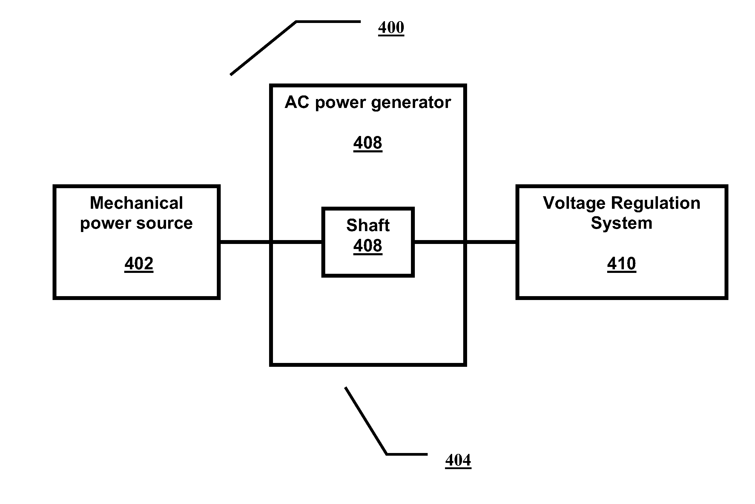
System and method for generating an alternating current output signal
a technology of alternating current and output signal, which is applied in the direction of motor control, dynamo-electric machines, engine control, etc., can solve the problems of inability to completely solve the problem of alternating current generators, inability to keep the shaft speed of generators constant, and inability to completely solve the problem of ac generators. to achieve the effect of substantially constant ac output peak voltag
- Summary
- Abstract
- Description
- Claims
- Application Information
AI Technical Summary
Benefits of technology
Problems solved by technology
Method used
Image

Examples
example 1
Testing of An Illustrative System
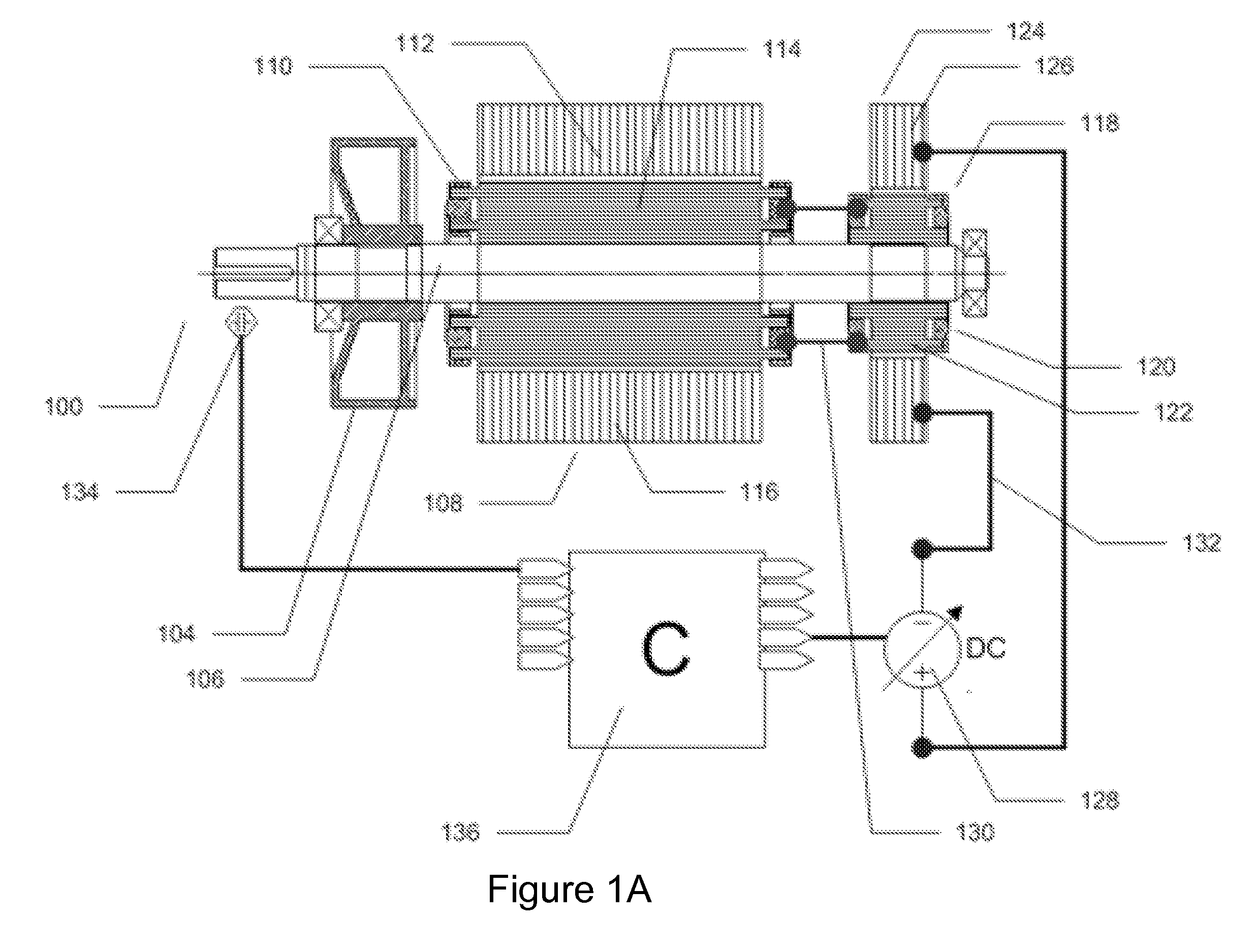
[0081]This Example describes a test performed on an exemplary, illustrative non-limiting system according to the present invention. The system featured a hybrid, dual winding three phase generator as is known in the art, which includes both a DC generator and an AC generator, product number ECO3-254 (Mecc Alte S.p.A., Italy); and a voltage regulation system based on a CQM-45 (Omron Inc., USA) Programmable Logic Controller (PLC). The set point voltage of the system was 285 Vac. The AC generator was powered by an electric motor connected to a variable speed motor driver. The speed of rotation of the AC generator shaft was then altered according to the speed of the motor. For each rotation speed, the excitation voltage of the auxiliary DC generator was changed, until the peak voltage of the AC output reached the set point value (285 Vac).
[0082]FIG. 5 shows the auxiliary excitation voltage values of the DC generator according to the speed of the shaft of...
example 2
Testing of An Illustrative System With Brushes
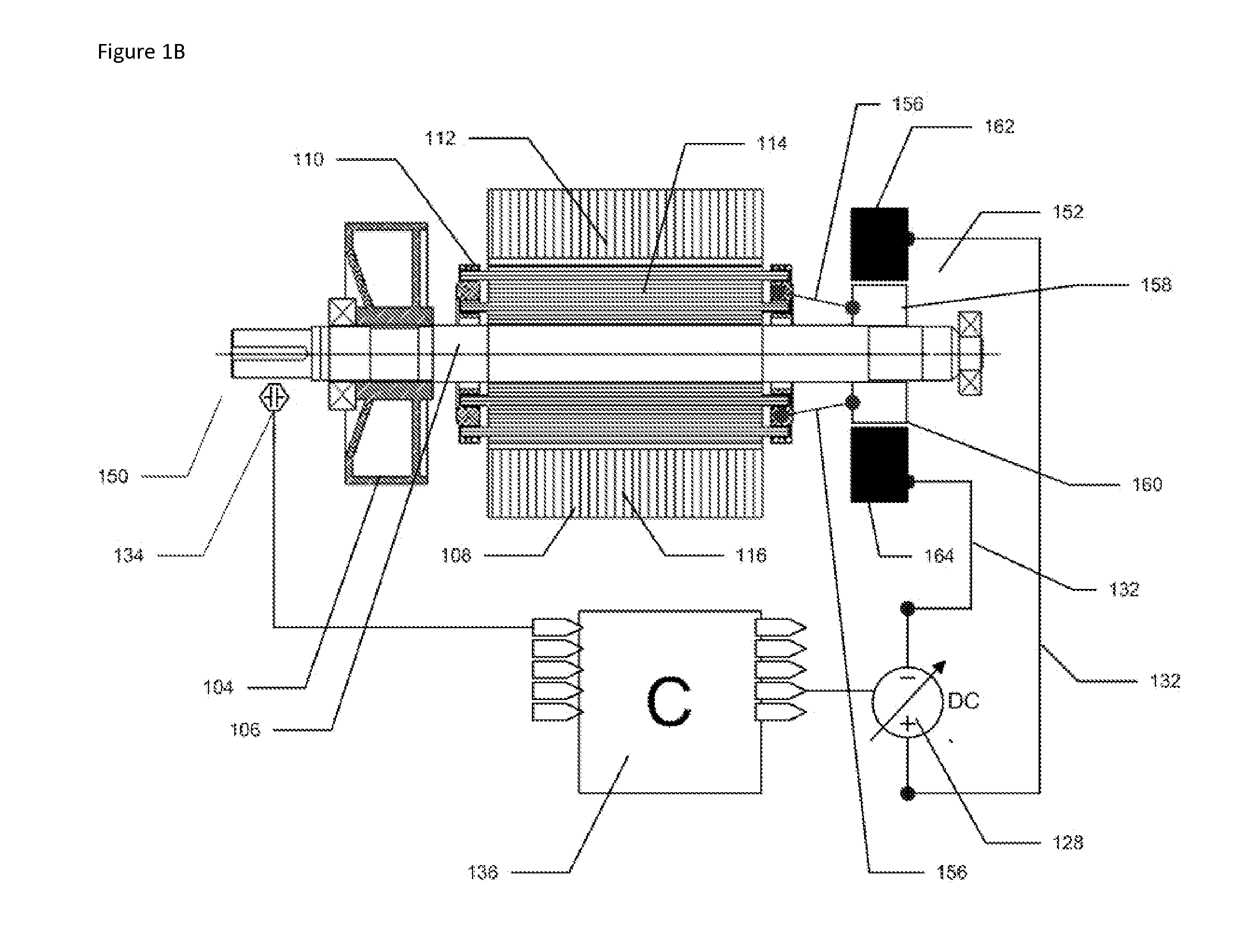
[0112]This Example describes a test performed on an exemplary, illustrative non-limiting system according to the present invention, according to an embodiment featuring a brushes mechanism as described above. The system featured a hybrid, dual winding three phase generator as is known in the art, which includes both a brushes mechanism and an AC generator, product number STC-3, 3 Kw 380V-Sphase generator, made by Fuan Lion Motor Co. Ltd., China; and a voltage regulation system based on a CQM-45 (Omron Inc., USA) Programmable Logic Controller (PLC). The set point voltage of the system was 285 Vac. The AC generator was powered by an electric motor connected to a variable speed motor driver. The speed of rotation of the AC generator shaft was then altered according to the speed of the motor. For each rotation speed, the excitation voltage of the brushes mechanism was changed, until the peak voltage of the AC output reached the set point val...
PUM
 Abstract
Description
Claims
Application Information