
Wind engine and wind power system

a technology of wind power generation and wind turbines, which is applied in the direction of renewable energy generation, electric generator control, greenhouse gas reduction, etc., can solve the problems of wind power generation efficiency, wind power generation efficiency is not high, and the ecological environment of the earth is damaged, so as to promote the wide use of wind power generation and reduce pollution or even eliminate the effect of pollution

Inactive Publication Date: 2010-05-06
WANG YING +1
View PDF10 Cites 26 Cited by
  • Summary
  • Abstract
  • Description
  • Claims
  • Application Information

AI Technical Summary

Benefits of technology

[0007]In view of the above-described problems, it is one objective of the invention to provide a wind engine and its wind power system and wind power generation system integrating new technical concept and components to solve the above-mentioned wind turbine and wind farm problems, and pursues a technical system that is a perfect combination of power and power generation to relieve the grave situation of scare mineral energy and to gradually replace the existing thermal power plants to become the mainstream electric energy supply model, and meanwhile to relieve or even eliminate pollution and damage to the ecologic environment of the earth, promote the wide use of wind energy power generation, and achieve the ideal purpose of creating a sound economic and social environment of the world featuring sustainable, good and healthy development.
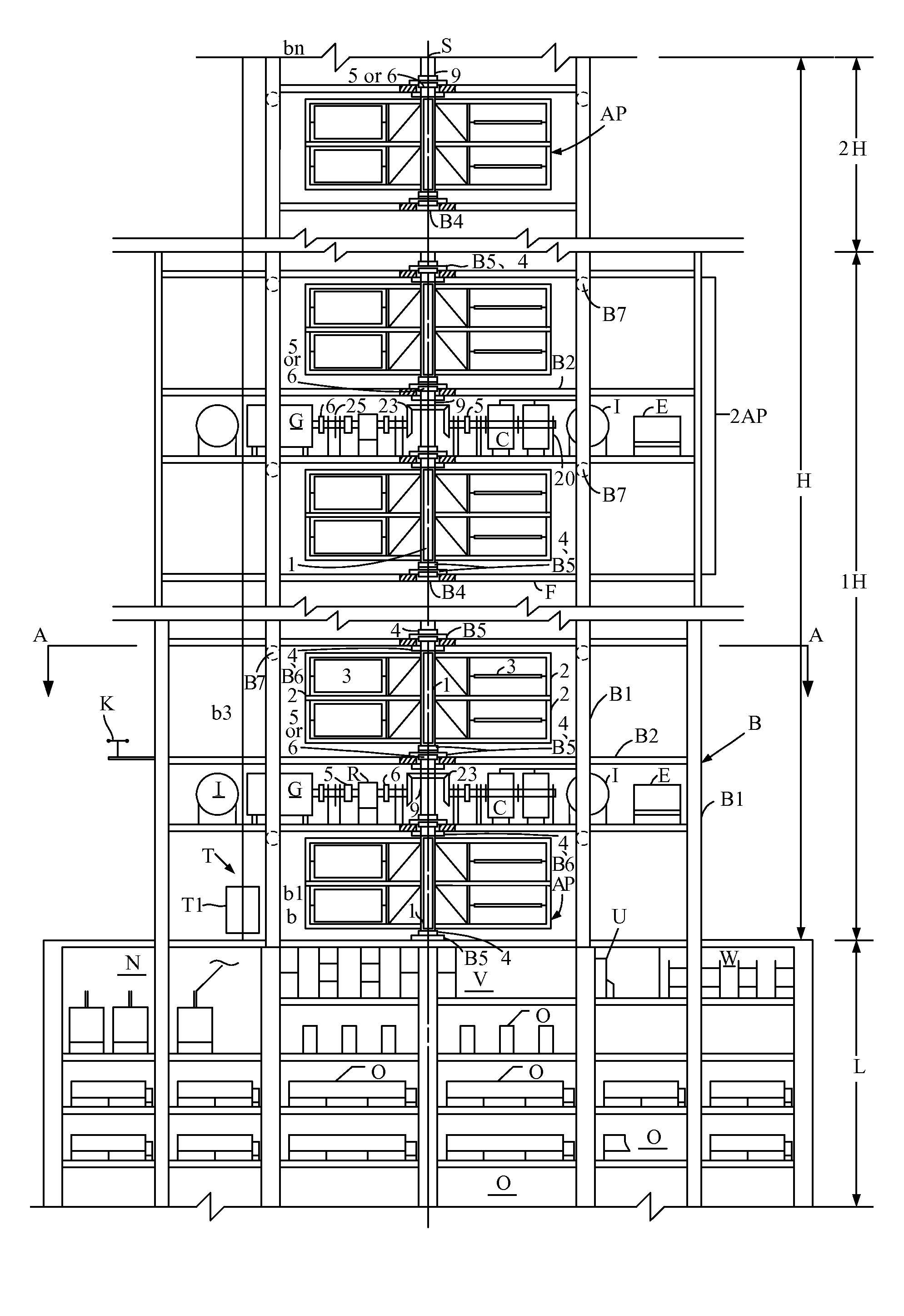
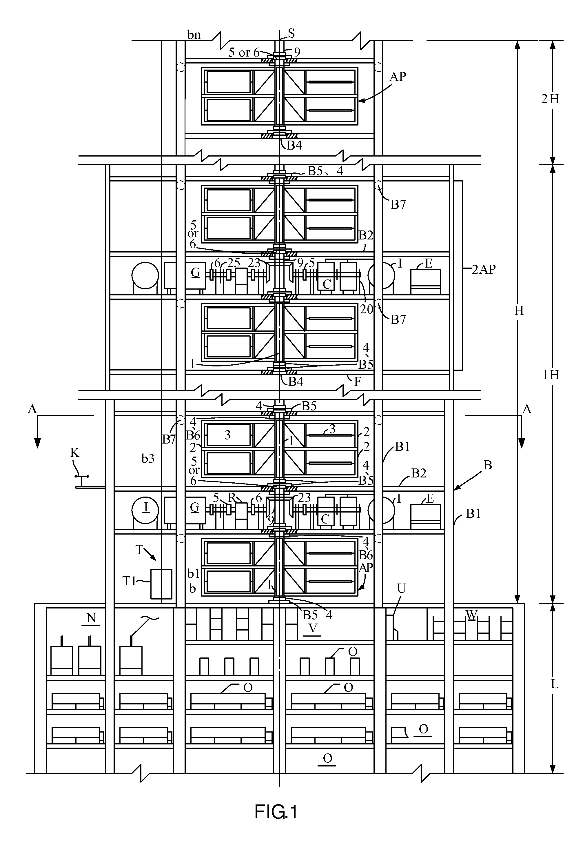
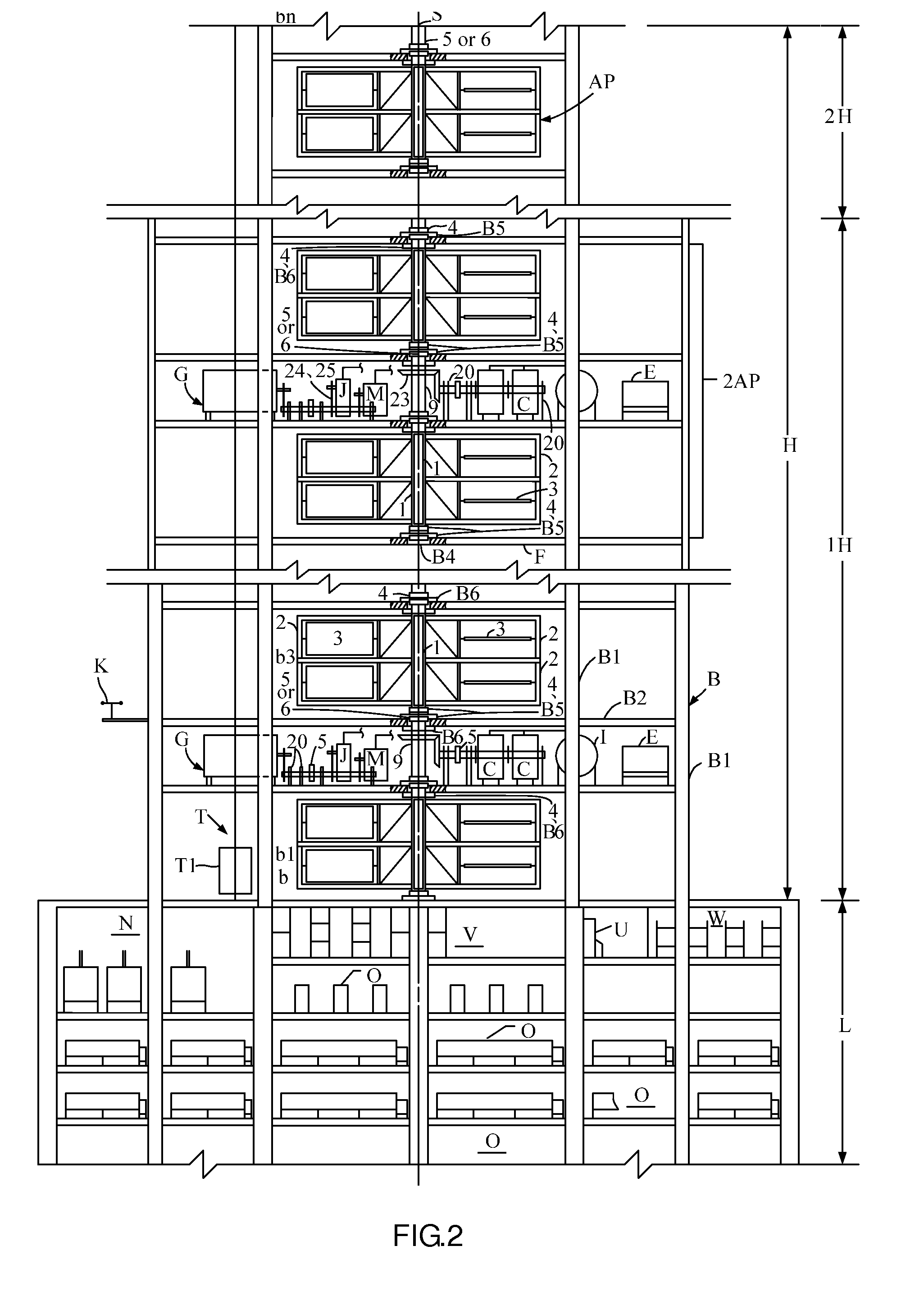
[0008]To achieve the above objective, in accordance with one embodiment of the invention, provided is a wind engine, comprising a vertically positioned central rotor; a power generation part; an opening adjustment positioner; a brake; a power distributor; a power switch, the vertically positioned central rotor has one unit of several groups of frameworks evenly distributed around it, or has at least two units of several groups of frameworks distributed longitudinally and consecutively along its length; each group of the frameworks is provided with at least one set of the power generation parts which can turn within a set range; a profile frame of the power generation parts has support shafts 3c of the same horizontal central line each positioned at ½ or ⅖ to ⅗ of the longitudinal height of the left and right side frames, and are installed with a bearing 3d onto the left and right columns 2c, 2d of the corresponding frameworks 2, to form a structure which is centered around the support shaft and can adapt to the wind direction changes, so that during the reversing wind stroke it will automatically reverse to be in a state where its entire plane is almost horizontal to the air flow direction without any air flow resistance, and during the fair wind stroke it will automatically return to a closed vertical state where it bears the pushing force perpendicular to the air flow, thereby driving the rotation of the entire system to form a wind engine; a bottom frame of the profile frame 3a has a set of reversing and return boosters 3g installed on one side that assists the power generation parts to reverse and lift and controls the reversing speed in case of a high wind speed; at columns 2c, 2d side of all groups of frameworks 2, there is the brake 8 for the power generation parts 3 for controlling the operation or stop of the wind engine and the opening adjustment positioner 7 for limiting the lifting angle of the power generation parts mounted on an integrated assembly bracket 2i; the brake 8 is electrically connected to the power distributor 21 installed on the lower shaft part 1f or upper shaft part 1e of the central rotor 1 via conductor or cable, and can control the make / break of the circuit via the power switch 22 of the power distributor 21, so that the brake 8 can release or limit the reversing of the power generation parts.

Problems solved by technology

For this type of wind turbine to meet the requirement for higher power output, the larger its blades, the higher the material strength and manufacture technical and bottleneck; since it is necessary to drive a large load immediately following startup, there should be a sufficient large torque; therefore the wind farm of such system shall be located in an area that has a strong wind force to achieve the conditions necessary for operation, and this is the key factor of the difficulty in wide application of wind power generation.
The wind speed necessary for normal operation and power generation of such wind turbines is about 10-22 m / s and lower wind speed will lead to lower power generation efficiency; however, if the wind speed exceeds 25 m / s, the wind turbine shall be cut out of work or the generator unit may be damaged; therefore, it has a narrower usable wind speed range, and the wind turbine has a lower efficiency because the system will not operate to generate power when the wind is weak or when there is no wind more often than not.
In addition, it needs an energy-consuming wind direction tracking and navigation unit, which reduces the efficiency of the wind turbine; furthermore, the wind farm for such wind turbines occupies a wide area of land, which wastes land resources.
To capture a stronger wind force, one independent huge tower each for a wind turbine is a costly waste, and the maintenance is difficult and costly as well; more over, its large rotating blades are fatal killers to numerous birds, causing another dangerous ecological disaster.

Method used


Image

  • Wind engine and wind power system
  • Wind engine and wind power system
  • Wind engine and wind power system

Examples


Embodiment Construction

[0080]Further description of the present invention will be given in the following in combination with the drawings and embodiments:

[0081]First, please refer to FIG. 1, which shows the composition of the wind energy power generating system described in claim 10. This is a stored energy power system which uses a support construction B of special design to develop into higher space to vertically integrate individual wind energy power engines (AP) to form unit(s) of wind energy power engines (2AP or 4AP) so as to generate and output greater power to drive the generator of higher power generation capacity to operate and generate power, and which can adjust and balance the wind energy power engines at different wind speeds to maintain stable and normal operation and can also store the wind energy, and furthermore, if necessary, can replace the wind energy power engine to drive the generator to maintain continuous operation for power generation in case of no wind or weak wind.

[0082]The sup...


PUM


Abstract

A wind engine has at least a central rotor (1) which has several groups of frameworks evenly distributed around it (2), each of the frameworks is provided with at least one set of power generation parts (3); the profile frame for the power generation parts is provided with a reversing and return booster (3g) for controlling the reversing speed, and each group of the frameworks is provided with a driver (8) and an opening adjustment positioner (7), and the brake releases or limits the reversing of the power generation parts by making or breaking the control circuit of the power distributor (21). The wind engine enables the power generation system to operate continuously and stably to generate power within the set varying range of different wind speed parameters and can improve power generation efficiency.

Description

CROSS-REFERENCE TO RELATED APPLICATIONS[0001]This application is a continuation of International Patent Application No. PCT / CN2007 / 001225, with an international filing date of Apr. 16, 2007, designating the United States, now pending. The contents of these specifications, including any intervening amendments thereto, are incorporated herein by reference.BACKGROUND OF THE INVENTION[0002]1. Field of the Invention[0003]The invention relates to the technical and equipment field of utilizing wind energy to generate and output power and electric energy, and more particularly to a wind engine, wind power system, and wind power generation system.[0004]2. Description of the Related Art[0005]The internationally known and used wind turbine generator systems (WTGS) generally have a design in which three blades are assembled in an impeller and a drive shaft and are coupled to a gear box to drive a motor. For this type of wind turbine to meet the requirement for higher power output, the larger it...

Claims


Application Information

Patent Timeline
IPC IPC(8): F03D3/02
CPCF03D3/067F03D7/06F05B2240/218F05B2240/40F05B2240/9121F05B2260/90Y10S415/905Y02E10/74F03D13/20H02S10/12F03D9/007F03D80/70F03D80/30Y02E10/728Y02E10/50
Inventor WANG, YINGLIN, QINGWAN
Owner WANG YING
Learn More