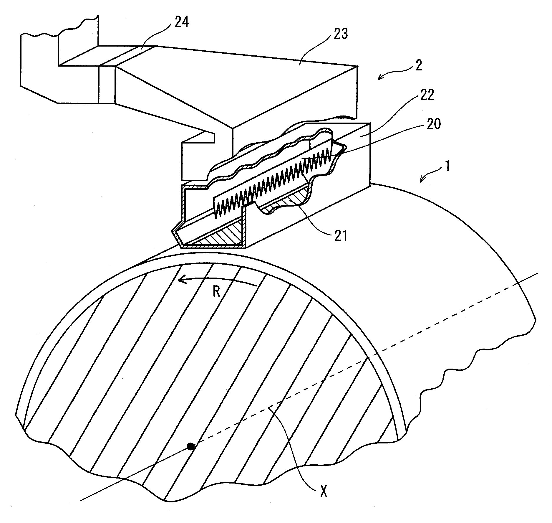
Charging device and image forming apparatus
a charging device and image forming technology, applied in the direction of electrographic process apparatus, instruments, corona discharge, etc., can solve problems such as image deletion, achieve the effects of preventing image deletion, increasing the structure complexity, size and cost of the device and apparatus, and suppressing the corrosion of the shielding member
- Summary
- Abstract
- Description
- Claims
- Application Information
AI Technical Summary
Benefits of technology
Problems solved by technology
Method used
Image
Examples
embodiment 1
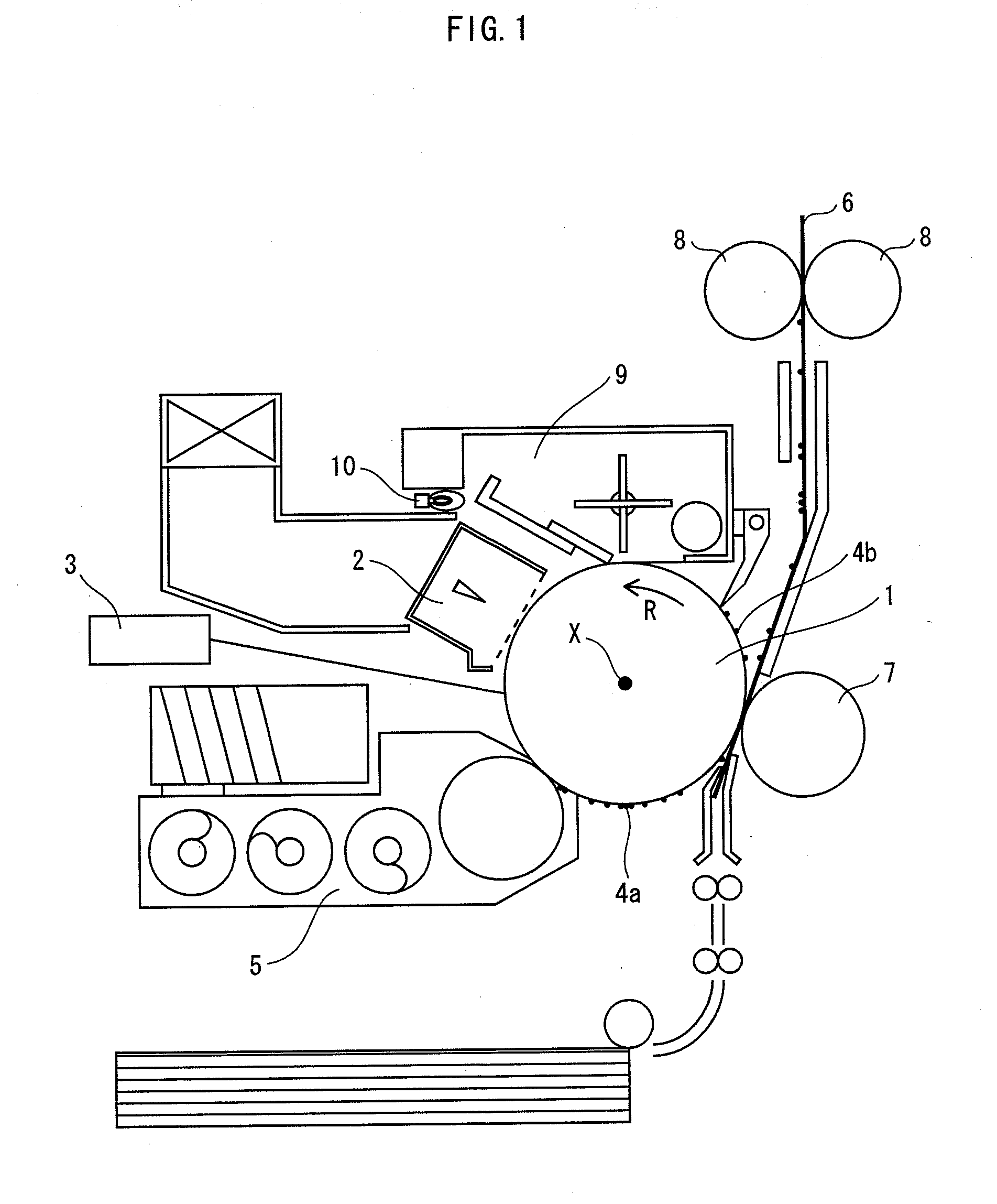
[0032]FIG. 1 is a schematic sectional view of an electrographic image forming apparatus consistent with Embodiment 1.
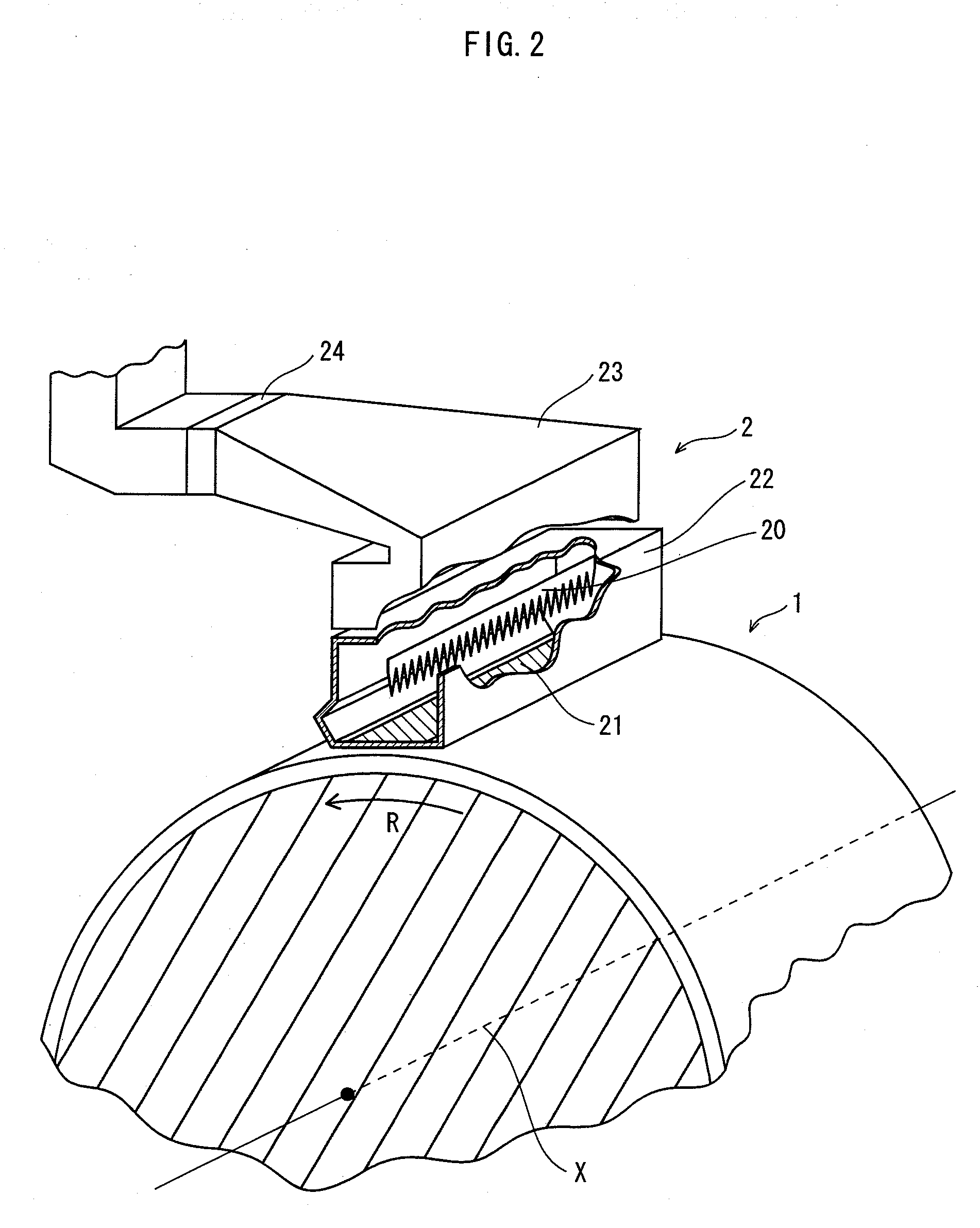
[0033]As shown in FIG. 1, the image forming apparatus consistent with Embodiment 1 includes: an image carrier 1, which is an OPC photoreceptor; a charging device 2 for uniformly charging the surface of the image carrier 1 at a predetermined potential; an exposure device 3 for forming an electrostatic latent image by directing laser light to the image carrier 1 having been charged at the predetermined potential; a developer device 5 for developing the latent image by attaching toner particles 4a mainly by the action of electrostatic force; a transfer device 7 for transferring the toner particles 4a from the image carrier 1 to a recording sheet 6, such as a sheet of copier paper, by electrostatic force or pressure; a fusing device 8 for fusing the transferred toner particles 4a on the recording sheet 6, by applying heat and pressure; a clearing device 9 for cleaning the...
embodiment 2
[0070]According to Embodiment 1 described above, one of the side plates has a cranked shape. Embodiment 2 differs from Embodiment 1 in that both the side plates have a cranked shape.
[0071]FIG. 8 is a cross sectional view showing the major part of a charging device 202 consistent with Embodiment 2. The cross section is taken along a plane perpendicular to the rotation axis x of an image carrier 1. FIG. 8 also shows a schematic representation of the electrical connection. The charging device 202 of Embodiment 2 is basically identical to the charging device 2 of Embodiment 1, except for the shape of the shielding case. Thus, the identical components are identified with the same reference numerals.
[0072]As shown in FIG. 8, the charging device 202 consistent with the present embodiment has a shielding case 222 and anti-ionic-wind sheets 25a and 25b each attached to the outer surface of either side plate of the shielding case 222. A discharge electrode 20 is connected to the high voltage ...
modification 1
[Modification 1]
[0088]According to Embodiment 1, one of the side plates of the shielding case has a bulged portion with a cranked outline, at a portion in the vicinity of the opening. According to Modification 1, the budged portion has a circularly curved outline instead of a cranked outline.
[0089]Similarly to FIG. 4 relating to Embodiment 1, FIG. 11 shows the section of a charging device 302 according to Modification 1, with the distribution of electric field strengths calculated by running simulations.
[0090]As apparent from FIG. 11, the charging device 302 consistent with Modification 1 is basically identical to the charging device 2 according to Embodiment 1, except for that the structure of a shielding case 322 is partly different from that of the shielding case 22. That is, the charging device 302 exhibits a similar electric field strength distribution and achieves similar advantageous effects as those of Embodiment 1.
PUM
 Abstract
Description
Claims
Application Information
 - R&D
- Intellectual Property
- Life Sciences
- Materials
- Tech Scout
- Unparalleled Data Quality
- Higher Quality Content
- 60% Fewer Hallucinations
Browse by: Latest US Patents, China's latest patents, Technical Efficacy Thesaurus, Application Domain, Technology Topic, Popular Technical Reports.
© 2025 PatSnap. All rights reserved.Legal|Privacy policy|Modern Slavery Act Transparency Statement|Sitemap|About US| Contact US: help@patsnap.com


