
Fan control system

a control system and fan technology, applied in computer control, temperatue control, dynamo-electric motor/converter starters, etc., can solve problems such as abnormal stopping of motors, and achieve the effects of suppressing pressure, reducing dynamic pressure, and keeping the rotational speed of fans low

Inactive Publication Date: 2010-05-06
DAIKIN IND LTD
View PDF11 Cites 14 Cited by
  • Summary
  • Abstract
  • Description
  • Claims
  • Application Information

AI Technical Summary

Benefits of technology

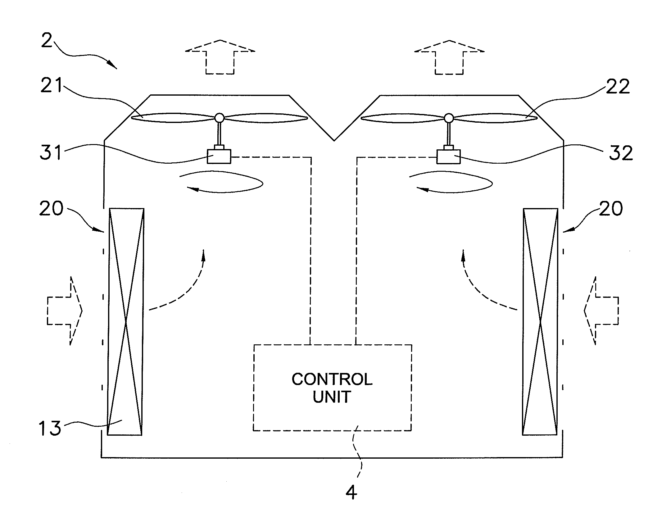
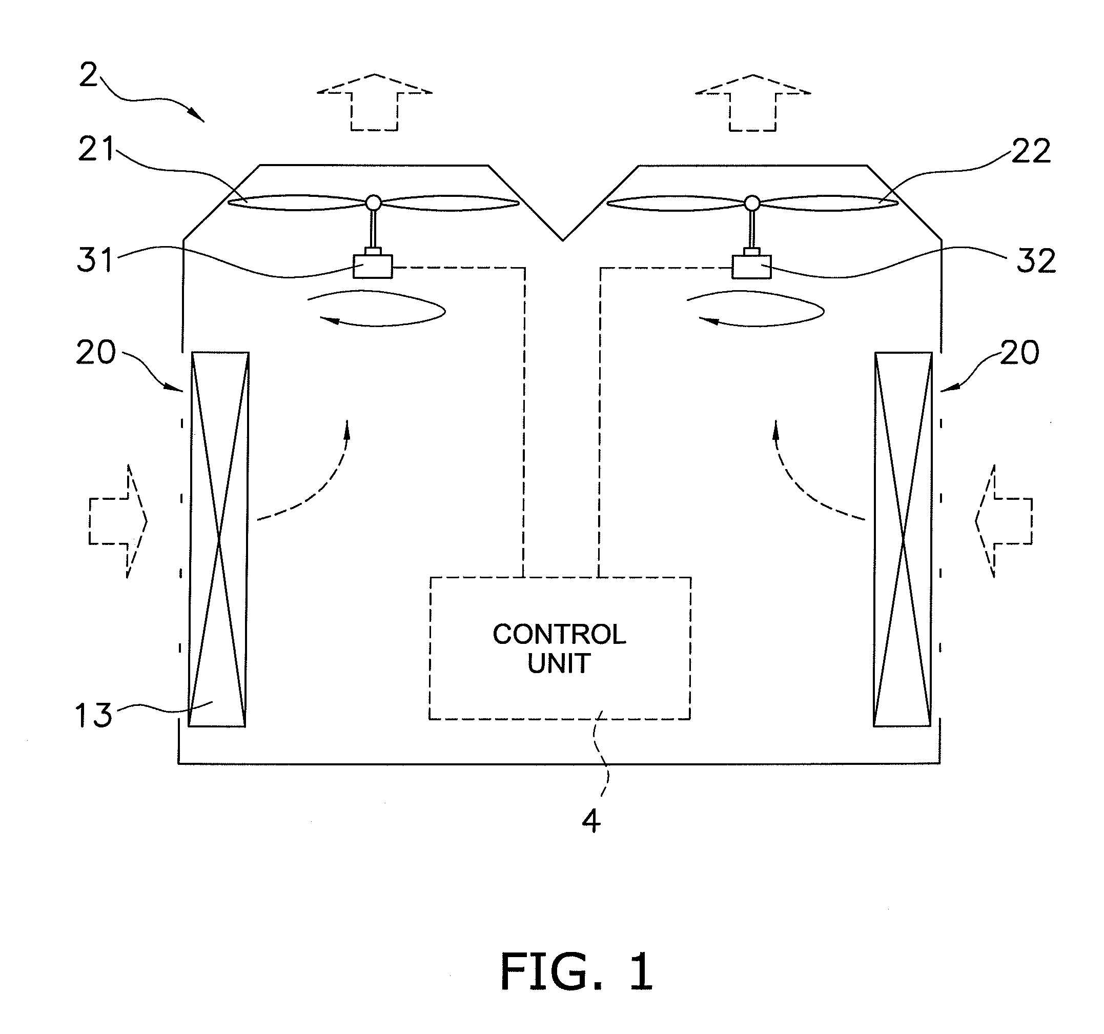
[0024]In the fan control system according to the first aspect of the present invention, the rotational speeds of the fans are kept low, which reduces the dynamic pressure on the suction side of the fan that started early and suppresses pressure that would otherwise work to rotate adjacent fans in reverse. In addition, even if the adjacent fans were to rotate in reverse, the rotational speeds thereof would be low and the load that is needed to change the rotational direction from reverse rotation to forward rotation at start-up would be small.
[0025]In the fan control system according to the second aspect of the present invention, it is possible to provide a difference in the required rotational speeds of the first fan and the second fan and thereby to equalize the dynamic pressures on the suction sides of the first fan and the second fan. As a result, the generation of a load owing to a dynamic pressure differential is suppressed.
[0026]In the fan control system according to the third aspect of the present invention, it is possible to provide a difference in the target rotational speeds of the first fan and the second fan and thereby to equalize the dynamic pressures on the suction sides of the first fan and the second fan. As a result, the generation of a load owing to a dynamic pressure differential is suppressed.
[0027]In the fan control system according to the fourth aspect of the present invention, the rate of increase of the dynamic pressure on the suction side of each of the fans decreases and the load applied to the adjacent fan also decreases.
[0028]In the fan control system according to the fifth aspect of the present invention, when the rotational speed is increased, the situation where the second fan rotates in reverse owing to the dynamic pressure on the suction side of the first fan does not arise, which makes it easier to start up and accelerate the second fan.
[0029]In the fan control system according to the sixth aspect of the present invention, when the rotational speed is increased, the situation where the second fan can no longer start up or accelerate owing to the dynamic pressure on the suction side of the first fan is prevented.

Problems solved by technology

Because outdoor fans are generally disposed outdoors, natural wind sometimes causes them to rotate in reverse when stopped; when the motor is started up in such a state, an overcurrent is sometimes generated in the inverter circuit, which causes the motor to stop abnormally.

Method used


Image

  • Fan control system
  • Fan control system
  • Fan control system

Examples


first modified example

[0057]A plurality of target rotational speeds (e.g., first target rotational speeds C1, C2) may be provided for each of the fans, that is, the first fan 21 and the second fan 22, such that the numerical values of the second target rotational speeds B1, B2 are larger than those of the first target rotational speeds C1, C2. Raising the rotational speed in steps in turn raises the dynamic pressure on the suction side in steps, which reduces the impact on adjacent fans.

second modified example

(Start-Up Limiting Rotational Speed)

[0058]In a case wherein a plurality of fans exist within the same air passageway, when the rotational speed of one of the fans reaches the prescribed rotational speed, the adjacent fans sometimes rotate in reverse owing to the dynamic pressure on the suction side. Here, when a fan operates in the state wherein it is rotating in reverse, there is a risk that a protective function will trip owing to an overload, an overcurrent, and the like, causing the fan to stop operating; therefore, it is preferable that the fan does not rotate in reverse prior to start-up or during operation. In the second modified example, when the first fan 21 is started up in the state wherein both the first fan 21 and the second fan 22 are at rest and then its rotational speed is increased, the rotational speed when the second fan 22 starts to rotate in reverse owing to the dynamic pressure on the suction side of the first fan 21 is stored in the memory of the microcomputer...

third modified example

(Startup Limiting Rotational Speed)

[0062]In a case wherein a plurality of fans exist within the same air passageway, when the rotational speed of one of the fans reaches the prescribed rotational speed, the protection function of the adjacent fans subject to dynamic pressure on the suction side may trip owing to an overload, an overcurrent, and the like, which makes those fans no longer able to start up or accelerate. To prevent such a situation, in the third modified example, when the first fan 21 is started up in the state wherein both the first fan 21 and the second fan 22 are at rest and then its rotational speed is increased, the rotational speed when the second fan 22 can no longer start up owing to the dynamic pressure on the suction side of the first fan 21 is stored in the memory of the microcomputer 40 as a first start-up limiting rotational speed. When the microcomputer 40 increases the rotational speed of the first fan 21, the first motor 31 is energized such that the va...


PUM


Abstract

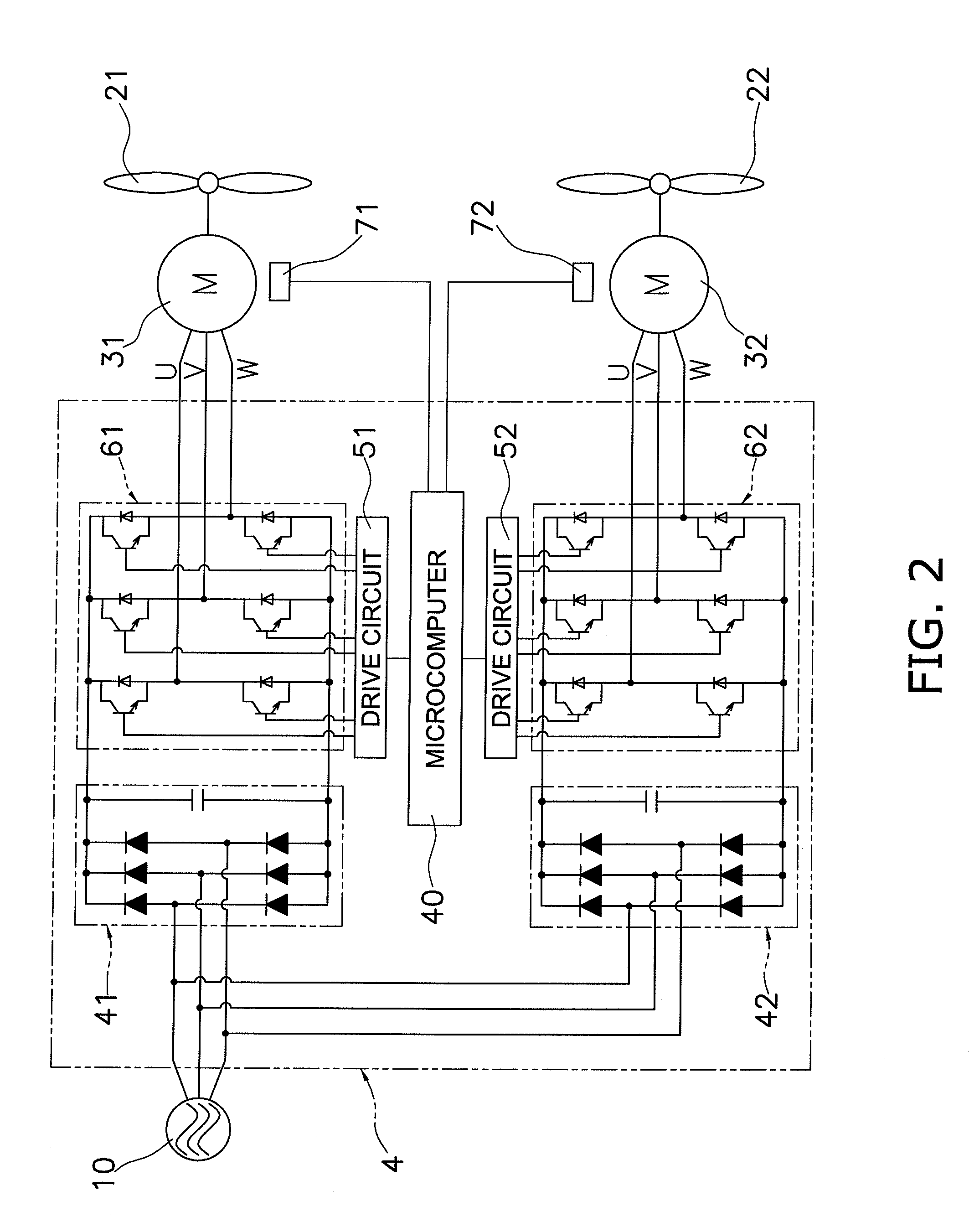
A fan control system includes first and second adjacent fans, first and second motors configured to rotate the first and second fans, and a control unit configured to control rotational speeds of the first and second motors in order to control rotational speeds of the first and second fans. The first and second motors are energized such that the rotational speeds of the first and second fans reach target rotational speeds prior to increasing the rotational speeds of the first and second fans to required rotational speeds. The target rotational speeds are lower than the required rotational speeds. The first and second motors are energized such that the rotational speeds of the first and second fans reach the required rotational speeds after the rotational speeds of the first and second fans reach the target rotational speeds.

Description

TECHNICAL FIELD[0001]The present invention relates to a fan control system, and more particularly relates to a fan control system that controls a plurality of fans.BACKGROUND ART[0002]In recent years, the motors that drive the fans of outdoor units of air conditioners (hereinbelow, abbreviated as outdoor fans) have been controlled by inverters, wherein rotational speed is controlled in accordance with instructions regardless of the external load's size. Because outdoor fans are generally disposed outdoors, natural wind sometimes causes them to rotate in reverse when stopped; when the motor is started up in such a state, an overcurrent is sometimes generated in the inverter circuit, which causes the motor to stop abnormally. One way of solving this problem is a method, which has already been disclosed (e.g., refer to Patent Document 1), that presets a permissible start-up rotational speed at which the fan can be started up even if it is rotating in reverse; with this method, if the f...

Claims


Application Information

Patent Timeline
Patent Type & Authority Applications(United States)
IPC IPC(8): G05B15/00F04D27/00F24F11/48F24F11/49F24F11/64F24F11/74F24F11/871F24F140/00H02P5/46H02P5/51
CPCF24F1/38F24F1/68F24F11/77F04D27/004F04D25/166F24F11/0001Y02B30/70
Inventor SATO, TOSHIAKIDOUMAE, HIROSHIKAGIMURA, SUMIO
Owner DAIKIN IND LTD
Learn More