
Fire suppression apparatus and method for generating foam

a technology of fire suppression apparatus and foam, which is applied in the direction of combustion process, combustion type, burner, etc., can solve the problems of reducing the velocity of the aqueous stream, the inability to smother fire with foam generated from air gas, etc., and achieves the effect of enhancing the velocity of the foam-forming liquid, enhancing uniform dispersion, and maximizing the entrainment of gas

Active Publication Date: 2010-05-13
FORCED GAS TECH
View PDF16 Cites 23 Cited by
  • Summary
  • Abstract
  • Description
  • Claims
  • Application Information

AI Technical Summary

Benefits of technology

[0011]The foam-forming liquid is sprayed into the inlet of a mixing manifold through at least one jet. The jet has a discharge nozzle having a cross-sectional area that is less than the cross-sectional area of the cavity of the mixing manifold. In one embodiment, the foam-forming liquid is injected into the mixing manifold through a plurality of jets. For example, from three to seven jets may be employed. The jets may be “free jets,” defined as a jet having a nozzle cross-sectional area that is less than ⅕ the cross-sectional area of the cavity of the mixing manifold, into which the jet is sprayed. While it is believed that a jet having a nozzle configuration, that is, an inlet tapering to a narrower discharge opening, creates a turbulent, high velocity cone of foam-forming liquid, which enhances foam creation in the mixing manifold, the jet may also be created by a hole or slot in an orifice plate.
[0013]The jet(s) are directed toward the outlet of the mixing manifold. It is believed to be advantageous to design the jet(s) to create a spray pattern that fills at least 50%, preferably at least 75%, most preferably substantially all of the cross-sectional area of the cavity of the mixing manifold.
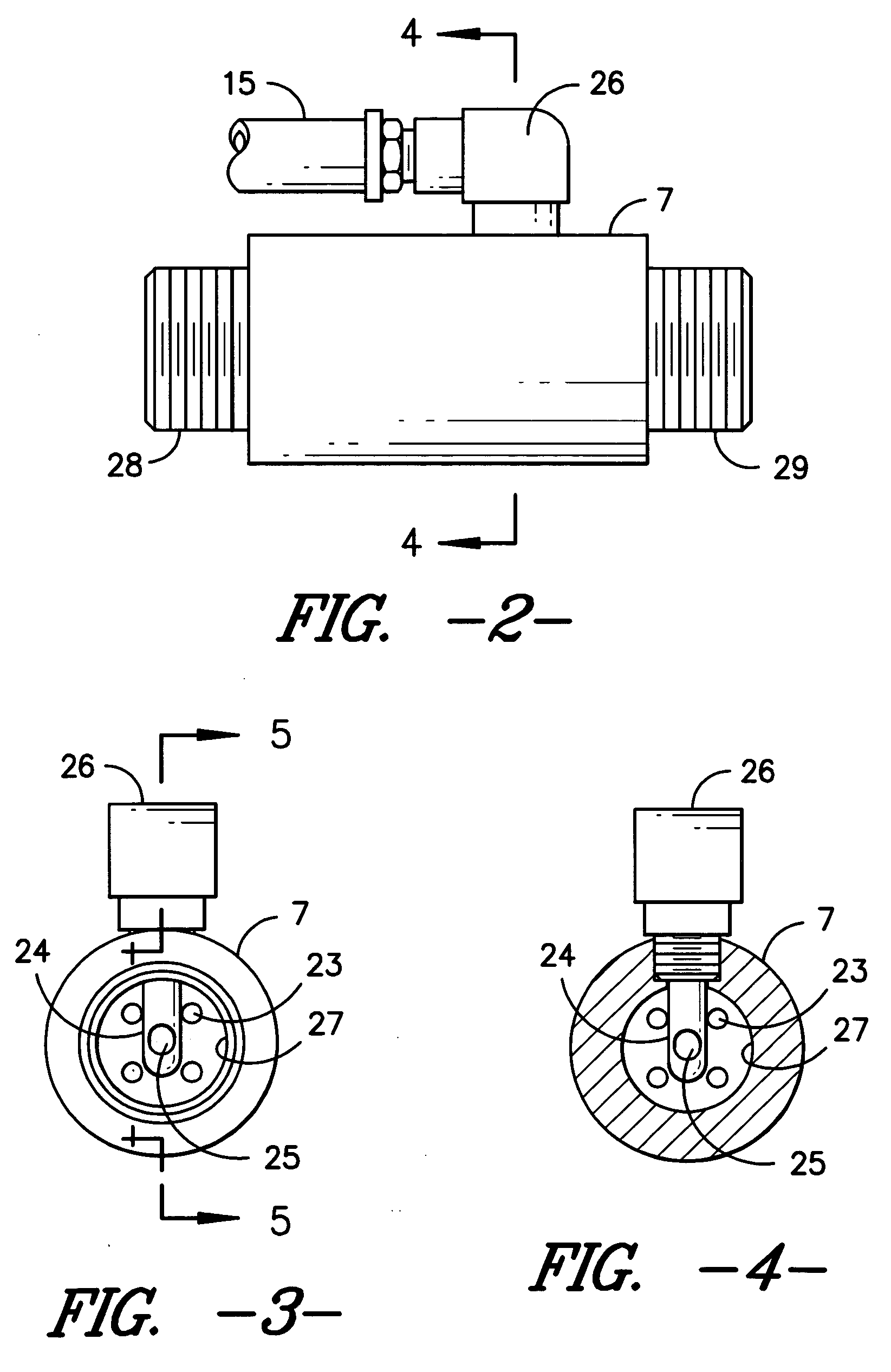
[0016]An object of the present invention is minimize the loss of momentum of the liquid, gas and foam, resulting from the angle of introduction of the gas, relative to the flow of liquid through the mixing manifold. Various means may be employed to accomplish the objective, including introducing the gas through a port located in the side of the mixing manifold at a downstream angle, through a cross-bar having an aperture facing downstream, or through a tube inserted substantially in the center of the flow of the liquid through the mixing manifold.
[0017]It is believed that the momentum of the fluids is best conserved when the gas is introduced into the mixing manifold at substantially the same angle as the direction of flow of the foam-forming liquid through the mixing manifold. Additionally, improvements in performance are realized when the gas is introduced into a location that is within ½ radius from the center of the cavity of the mixing manifold, wherein the radius is that of the cavity at the point of introduction of the gas, measured perpendicular to the flow of the liquid. In one embodiment, the gas is introduced at substantially in the center of the flow of the liquid through the mixing manifold, with an aperture facing downstream, such as through a tube fashioned in the shape suggesting a “periscope.”
[0019]The mixing manifold has an inlet, a cavity, an outlet, as well as means to introduce the gas into the cavity of the mixing manifold. In one embodiment of the invention, the mixing manifold has a “flow through” design, characterized by (i) a cavity that is substantially straight between the inlet and outlet, that is, it is substantially free from bends and curves, and (ii) the outlet is at the downstream end of the cavity, that is, the outlet does not project into the cavity to cause recirculation of the liquid, gas or foam. By way of example, the mixing manifold may have a cylindrical cavity, with an inside diameter of from 1 to 2 inches. In one embodiment of the invention, the diameter of the mixing manifold from the point at which the gas is introduced to the outlet of the mixing manifold is substantially the same, thereby avoiding destabilizing shear, which can cause rupture or collapse of the foam.
[0021]By selecting from and combining the aforementioned features, it is possible to dramatically increase the velocity of the foam-forming liquid introduced into the mixing manifold, to position the jet(s) to direct a high-velocity cone of the foam-forming liquid into close proximity to the point of introduction of the gas into the mixing manifold, and to create a spray pattern of the foam-forming liquid that maximizes entrainment of the gas. Furthermore, it is possible to introduce the gas into the cavity of the mixing manifold at a location to enhance uniform dispersion, and in a direction to minimize the loss of momentum of the fluids. The turbulence and momentum created in the mixing manifold results in high-quality foam being formed, which is propelled along the length of hose and expelled from the nozzle at a high-velocity.

Problems solved by technology

There are a number of drawbacks associated with foam generating nozzles.
Since air contains oxygen, foam generated from using air as the gas is not ideal for smothering a fire.
The principle of conservation of momentum results in a decrease in the velocity of the aqueous stream.

Method used


Image

  • Fire suppression apparatus and method for generating foam
  • Fire suppression apparatus and method for generating foam
  • Fire suppression apparatus and method for generating foam

Examples


Embodiment Construction

[0027]Without limiting the scope of the invention, the preferred embodiments and features are hereinafter set forth. All United States patents cited in the specification are incorporated by reference. Unless otherwise indicated, the conditions are 25° C., 1 atmosphere of pressure, 50% relative humidity, and the percentage of materials in compositions are by weight. Nozzle diameters for non-circular nozzles, such as slots, are calculated across the shorter dimension. In the case of multiple nozzles having non-uniform nozzle diameters, an average nozzle diameter is calculated using an area weighting, that is, each nozzle diameter measurement is weighted by the area at the discharge point of the nozzle.

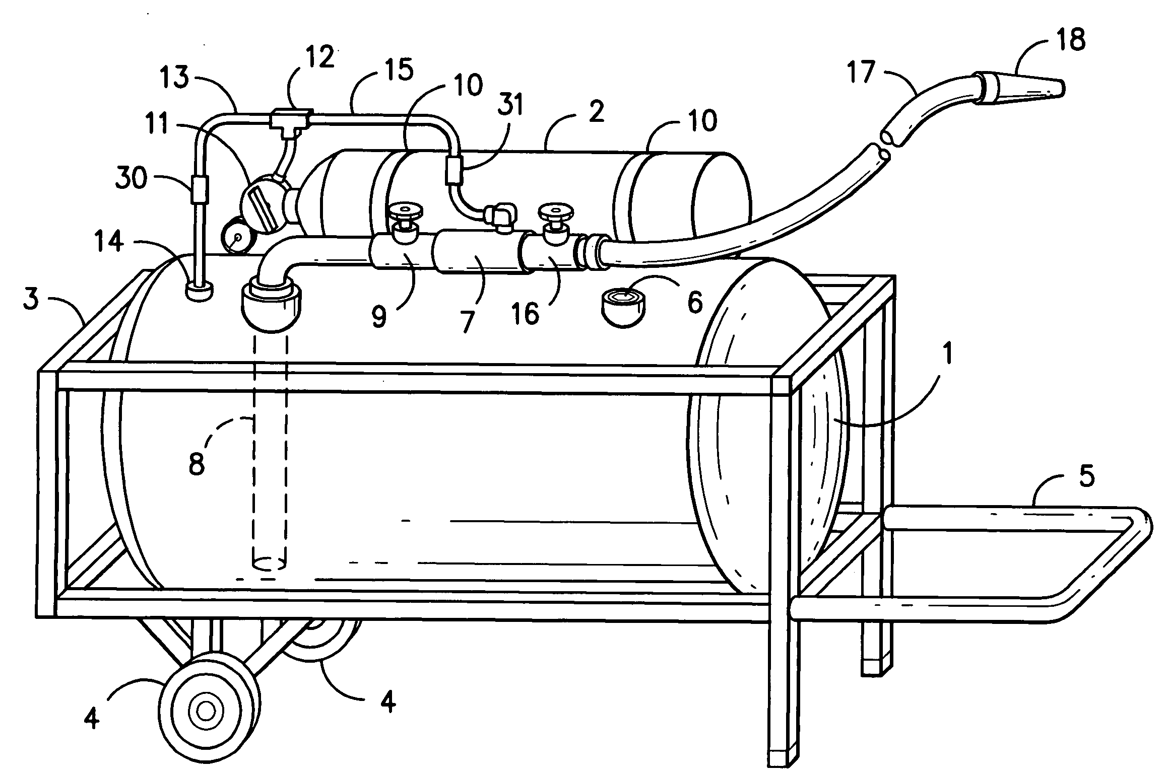
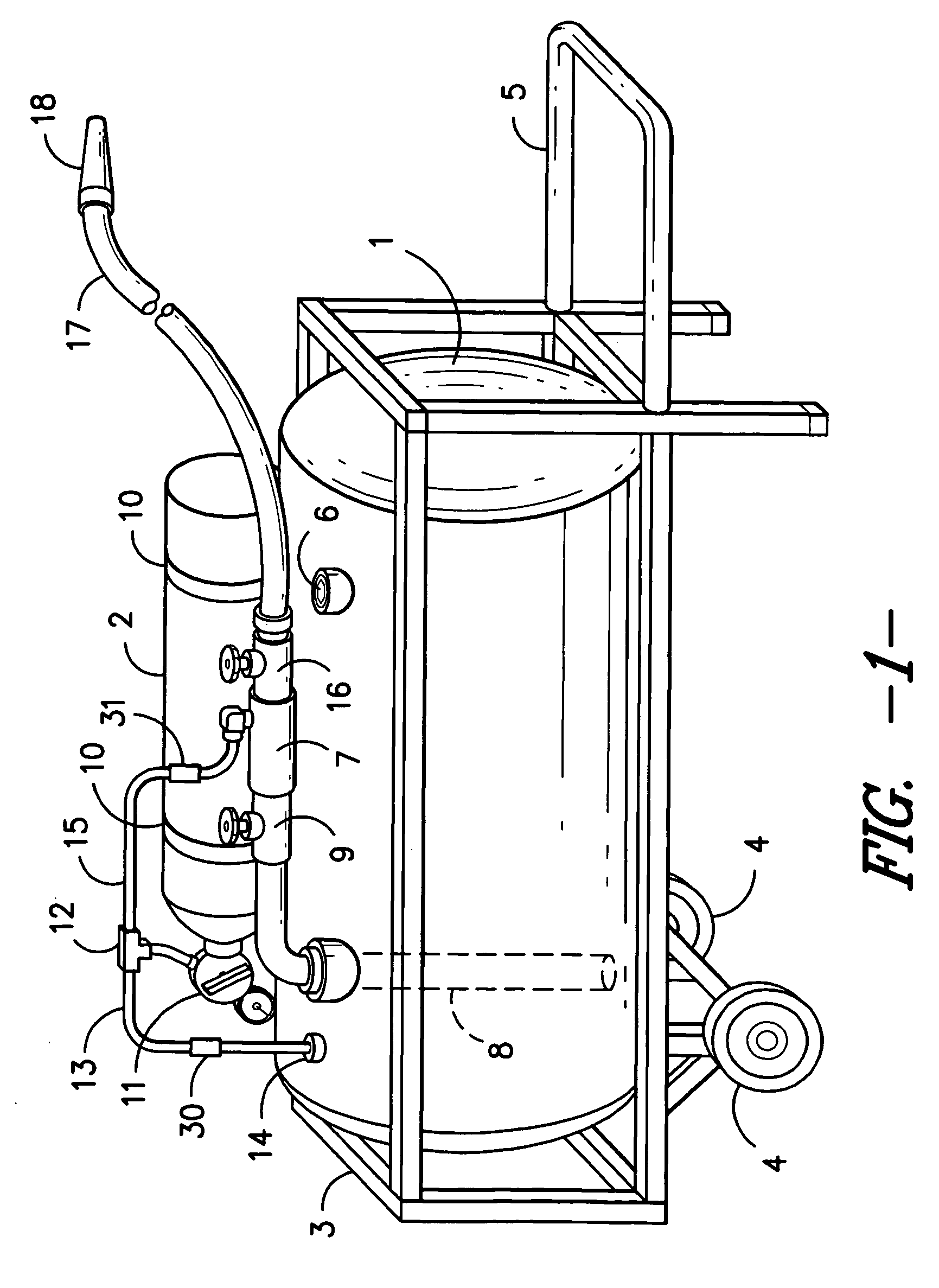
[0028]Referring to FIG. 1, the fire suppression apparatus has liquid tank 1 and compressed gas tank 2, which are mounted on frame 3. Frame 3 includes wheels 4 and handle 5, for manual transport of the apparatus to the scene of a fire. It is also within the scope of the invention for the ...


PUM


Abstract

A fire suppression apparatus and method of generating foam are provided in which a foam-forming liquid is introduced under high velocity and pressure into a mixing manifold through a plurality of jets, and a non-combustible gas is introduced under high velocity and pressure into the center of the mixing manifold, downstream of the jets and in the direction of flow of the foam-forming liquid. The foam generated in the mixing manifold is discharged through a hose and nozzle connected to the mixing manifold. The apparatus may be a self-contained unit, supported on a frame, with its own supply of foam-forming liquid and non-combustible gas.

Description

BACKGROUND OF THE INVENTION [0001]This invention is directed to a portable, fire suppression system, wherein a foamable liquid and a non-flammable compressed gas are combined in a manifold to generate foam.[0002]It is well known that the application of foam is useful to suppress fires. The foam is generated at the site of the fire, typically by mixing together a stream of water containing a suitable foaming agent and air. The quality of the foam, the liquid to gas ratio of the foam, the ability to use non-combustible gases, and the distance that the foam can be sprayed are factors relevant to the design and operation of fire suppression equipment.[0003]Carroll et al., U.S. Pat. No. 5,058,809 is representative of a foam generating nozzle designed to aspirate ambient air into a flowing aqueous stream containing a foam producing agent. Foam is produced and discharged from the outlet of the nozzle. It is also known to incorporate a deflection or impingement structure in a foam-generatin...

Claims


Application Information

Patent Timeline
Patent Type & Authority Applications(United States)
IPC IPC(8): B05B7/04
CPCA62C5/022B05B1/14B05B7/0031Y10S261/26A62C13/66Y10S261/12A62C13/003A62C31/12A62C31/02
Inventor HENRY, DARREN SEAN
Owner FORCED GAS TECH
Learn More