Detection of magnetic beads using a magnetoresistive device together with ferromagnetic resonance

a magnetoresistive device and magnetic beads technology, applied in the field of magnetic field measurement, can solve the problems of affecting the locked-in signal, 1/f noise is very significant, and the detection sensitivity can be usually improved, and the signal band width is narrow.

Active Publication Date: 2010-05-13
HEADWAY TECH INC
View PDF8 Cites 11 Cited by
  • Summary
  • Abstract
  • Description
  • Claims
  • Application Information

AI Technical Summary

Benefits of technology

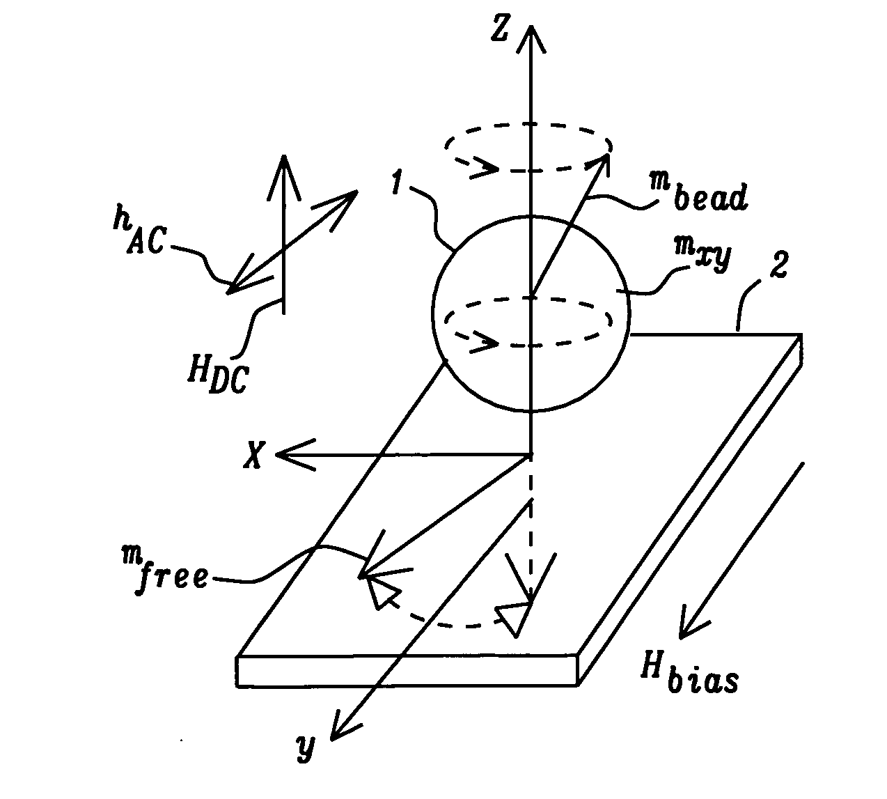
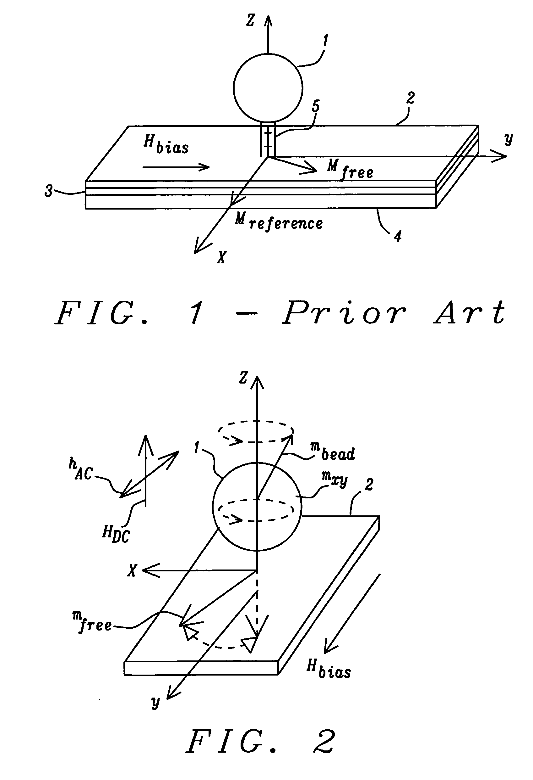
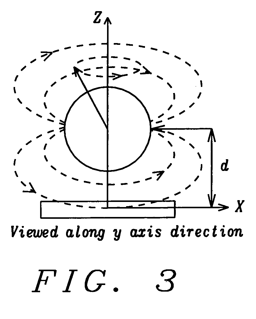
[0043]These objects have been achieved by exciting FMR (ferromagnetic resonance) in the bead and then detecting the rotating magnetic field that the bead emits while in the resonance state. Our preferred means for detecting said rotating field has been a magneto-resistive detector such as a GMR (giant magnetic resistance) or TMJ (tunneling magnetic junction) device, though the method can be effectively used with any device capable of detecting magnetic fields as low as 1 Oe that are oscillating at frequencies in the MHz to GHz range. As a practical matter, the lowest field that can be used will be determined by the intrinsic noise discrimination and detection sensitivity of the sensor. Additionally, the detection sensitivity can usually be improved by narrowing the band width of the signal that is being detected.

Problems solved by technology

A potential problem common to all the previously published or patented bead-MR sensor detection methods is that they are prone to fluctuations in the magnetic signal.
Since all these detection methods are mainly practiced in the low frequency region from several Hertz to several kHertz, 1 / f noise is very significant.
Although the lock-in technique can successfully suppress the noise from the electrical sources by its narrow bandwidth, the noise from magnetic sources, for example Barkhausen noise, popcorn noise and telegraph noise cannot be prevented from affecting the locked-in signal.
These variations will also cause fluctuations of the amount of the bead magnetic field going into the sensor.
With all the noise sources added together, these can be quite large and can cause significant signal fluctuations to inhibit practical binding assay applications that are based on the detection of the absolute field strength.
Another problem specifically for the field cancellation method is that a magnetic field needs to be applied in the sensing direction, i.e. X axis, to magnetize the magnetic beads and thus generate the cancellation field.
However, this mode requires a relatively large sensor size.
A low bias field, Hbias, or no bias field may be needed, which can easily lead to instability in a micron size sensor because of weak or no free layer domain control.
This noise can be more than 10 dB over the sensor's Johnson noise level in a micron size multilayer device and it will severely degrade the SNR of the sensor.

Method used


Image

  • Detection of magnetic beads using a magnetoresistive device together with ferromagnetic resonance
  • Detection of magnetic beads using a magnetoresistive device together with ferromagnetic resonance
  • Detection of magnetic beads using a magnetoresistive device together with ferromagnetic resonance

Examples


embodiment 1a

1. Embodiment 1A

[0074]Referring to FIG. 5A, the magnetic bead 1 is attached to the MR sensor 2 through biological or chemical binding pair 5 following a recognition process. Two permanent magnets 6 on the sides of the sensor provide a biasing field in the MR sensor to orient the sensing layer magnetization in the Y axis direction. A static field HDC is applied perpendicular to the sensor plane in the Z axis direction. This static field determines the FMR frequency of the bead magnetic moment. It also magnetizes the bead when the bead is super-paramagnetic. A stripe line (or lines) 7 exists underneath the sensor or between the sensor and the bead, where an AC current IAC is used to produce an AC magnetic field hAC in the Y axis direction to excite the FMR of the bead magnetic moment. The bead FMR then produces a rotating component in the XY plane. The MR sensor 2 detects the oscillating magnetic field

embodiment 1b

2. Embodiment 1B

[0075]Referring to FIG. 5B, every other aspect is the same as embodiment 1A except that the AC magnetic field hAC in the Y axis direction is generated not by stripe line (or lines), but externally by other means. For example, RF coils or electromagnetic waves in a microwave cavity.

embodiment 1c

3. Embodiment 1C

[0076]Referring to FIG. 5C, every other aspect is the same as embodiment 1A except that biasing DC field Hbias is applied externally or generated by the anisotropy field of the sensor. HDC (and Hbias as well if applied externally) determines the FMR frequency of the bead magnetic moment.


PUM


Abstract

A method and apparatus for detecting the presence of magnetic beads is disclosed. By providing both a static magnetic field and a magnetic field that alternates in the MHz range, or beyond, the bead can be excited into FMR (ferromagnetic resonance). The appearance of the latter is then detected by a magneto-resistive type of sensor. This approach offers several advantages over prior art methods in which the magnetic moment of the bead is detected directly.

Description

FIELD OF THE INVENTION[0001]The invention relates to the general field of magnetic field measurement with particular reference to that of magnetic beads that have been selectively bound to biological structures and / or large molecules.BACKGROUND OF THE INVENTION[0002]The invention discloses a methodology for detecting magnetic beads, magnetic particles and magnetic nano-particles by inducing ferromagnetic resonance (FMR) of their magnetic moment and by using a magneto-resistive (MR) sensor to detect the magnetic field produced by the FMR. Binding these magnetic beads or particles to biological or chemical molecules thus enables the presence of these molecules to be detected. In the form of a binding assay, where a matrix of MR sensors are patterned, this method can be used to identify the presence of a molecule of interest as well as to quantify its population. This method can address many other issues in the prior art that also utilize magnetic bead labeling and MR sensing, thus mak...

Claims


Application Information

Patent Timeline
Patent Type & Authority Applications(United States)
IPC IPC(8): G01R33/20
CPCG01N24/088G01R33/5601G01N24/10
Inventor ZHOU, YUCHEN
Owner HEADWAY TECH INC
Why Eureka
Try Eureka