Method for radar monitoring of wake turbulence

a radar and wake turbulence technology, applied in the direction of instruments, measurement devices, climate sustainability, etc., can solve the problems of not being able to determine whether the turbulence is particularly dangerous, not being able to operate correctly in clear weather,

Inactive Publication Date: 2010-05-13
THALES SA
View PDF31 Cites 13 Cited by
  • Summary
  • Abstract
  • Description
  • Claims
  • Application Information

AI Technical Summary

Benefits of technology

[0010]An aim of the invention is to propose a scheme making it possible, within the general context of airport traffic, to determine for a given airplane whether it is a sufficient distance from the airplane in front on its route so as not to experience the effects of the wake turbulence caused by the airplane in front while itself being in a vulnerable situation, in the takeoff or landing phase for example.

Problems solved by technology

Such turbulence is indeed particularly dangerous when the airplane which passes through it is in a situation of vulnerability, such as that which it experiences during the takeoff and landing phases, in particular at the point of entry into the ILS (i.e. “Instrument Landing System”) guidance zone for runway approach on landing, while it is situated a relatively small distance from the ground and in relatively congested navigation zones.
Faced with the constant and rapid increase in air traffic and with the arrival of new wide-bodied airplanes (Airbus A380 and Boeing B747-8), a dual problem arises related to the following two conflicting constraints:a first constraint gives expression to the fact that a wide-bodied airplane produces greater wake turbulence than a medium-bodied or narrow-bodied airplane.
However this solution, in addition to the fact that it requires the installation of relatively sophisticated guidance equipment, lacking in many airports, furthermore does not make it possible to determine whether the safety distance applied in this or that circumstance is a just sufficient distance or whether conversely it is too widely estimated.
The major drawback of this type of sensor for operational use is that it can only operate correctly in clear weather.
In fog and rain, the Lidar can no longer be employed.
In particular, the Lidar is incapable of measuring certain details on the geometry of the turbulence spiral which make it possible in particular to determine its state of fading so that insufficient knowledge of the detected turbulence is obtained.
Moreover, current Lidar systems are not able to monitor, in a time span compatible with operational requirements, a sufficiently wide sector of space to allow effective monitoring of an airport zone.

Method used


Image

  • Method for radar monitoring of wake turbulence
  • Method for radar monitoring of wake turbulence
  • Method for radar monitoring of wake turbulence

Examples


Embodiment Construction

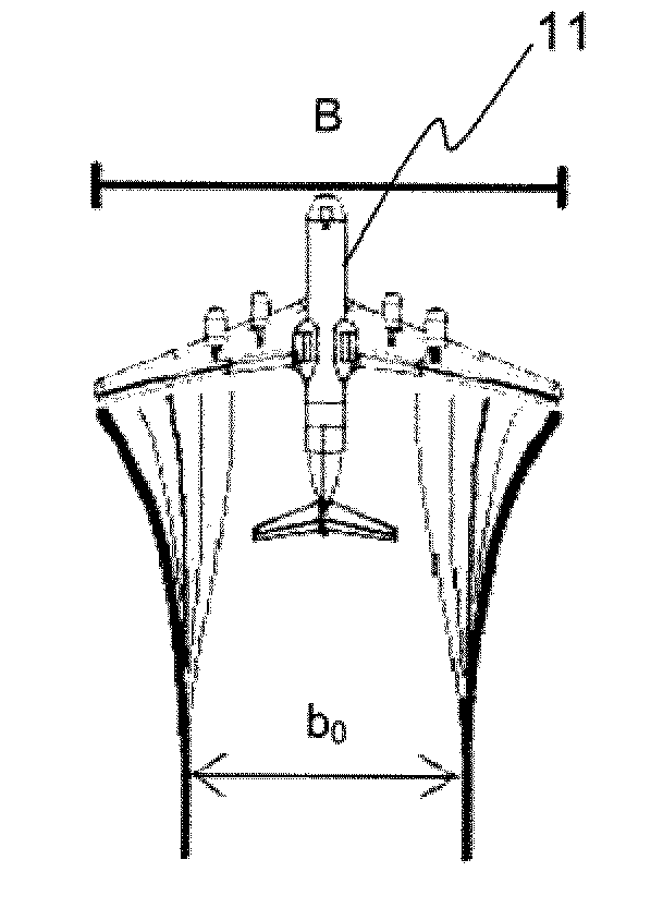
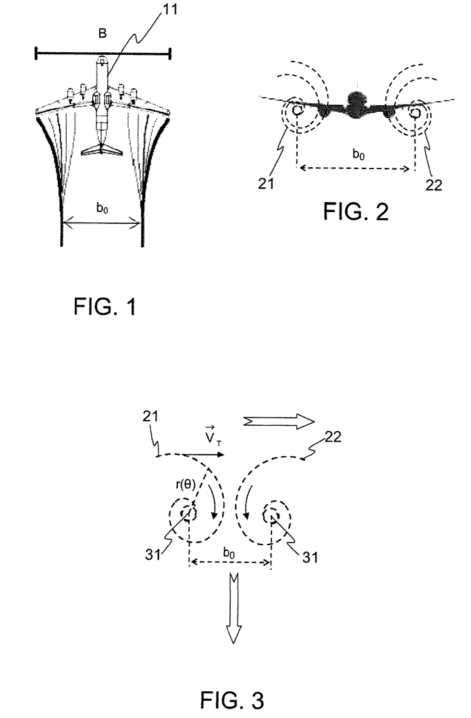
[0036]FIGS. 1 to 4, which illustrate in a schematic manner the wake turbulence phenomenon created by an aircraft 11, are considered initially. As illustrated by these three figures, the wake turbulence is materialized by the creation to the rear of the aircraft of two swirls 21 and 22 (vortices) which cause oppositely directed rotations of the air mass. One thus speaks of “counter-rotating” eddies.

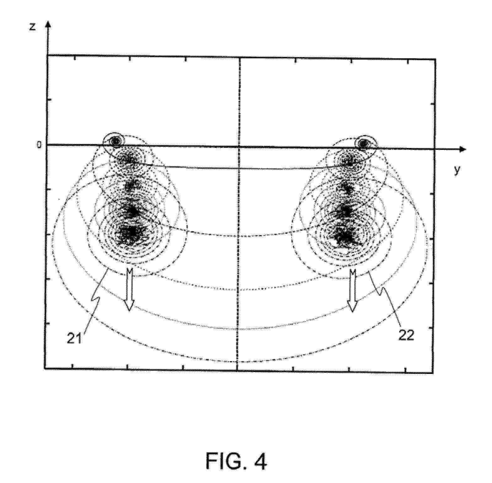
[0037]Each eddy 21, 22 takes the form of a spiral whose points are situated with respect to the center at a distance r(θ) varying exponentially as a function of the number of revolutions performed in order to join the point under consideration to the center. It is thus possible to write the relation:

r(θ)=a·ebθ for θ varying from 0 to Nπ (N integer).   [1]

[0038]where a and b represent the geometric parameters of the spiral.

[0039]Each eddy is furthermore characterized by its nucleus 31 of radius rc.

[0040]It is known to evaluate the danger related to the wake turbulence caused by an aircraft,...


PUM


Abstract

The present invention relates to a method for detecting and grading the state and the evolution of wake turbulence caused by an aircraft, on the basis of the radar signals reflected by this turbulence, these signals being analyzed through analysis cells of given dimension in terms of distance and bearing. This method mainly comprises:
    • a first preliminary detection step proper for detecting and locating turbulence in a cell,
    • a second step for determining the strength of the detected turbulence,
    • a third step for determining the age of the detected turbulence as well as the geometric parameters which characterize it.
The method according to the invention advantageously makes it possible to detect wake turbulence and to determine at one and the same time the position and the strength of the latter as well as its stage of evolution.
The invention applies in particular to the field of air traffic control and air safety in general.

Description

CROSS REFERENCE TO RELATED APPLICATIONS[0001]The present application is the U.S. National Phase of International Patent Application Serial No. PCT / EP2008 / 055864, filed May 13, 2008, which claims the benefit of French Patent Application Serial No. 07 / 03479, filed May 15, 2007, both of which are hereby incorporated by reference in their entireties.FIELD OF THE INVENTION[0002]The present invention relates to the field of air traffic control and air safety in general. It relates more particularly to the safety, rules which govern the relative distances between aircraft following one behind another along one and the same air corridor, notably during the takeoff phases and during the approach and landing phases.BACKGROUND OF THE INVENTION[0003]In the field of air traffic control, the safety distances between airplanes, standards dictated by the ICAO (International Civil Aviation Organization), have been established so as to avoid the dangers related to the encountering by airplanes of the...

Claims


Application Information

Patent Timeline
Patent Type & Authority Applications(United States)
IPC IPC(8): G01S13/95
CPCG01S13/64G01S13/953G01S13/951Y02A90/10
Inventor BARBARESCO, FREDERIC
Owner THALES SA
Why Eureka
Try Eureka