Cold-start engine loading for accelerated warming of exhaust aftertreatment system

a technology of exhaust aftertreatment and cold-start engine, which is applied in the direction of exhaust treatment electric control, machines/engines, mechanical equipment, etc., can solve the problems of generating a large amount of overall tailpipe hydrocarbon emissions, affecting the cooling effect of the engine, and affecting the cooling effect of the exhaust system, so as to reduce the catalyst light-off times and reduce the overall tailpipe nitrogen oxide emissions generated during engine cold-start.

a technology of exhaust aftertreatment and cold-start engine, which is applied in the direction of exhaust treatment electric control, machines/engines, mechanical equipment, etc., can solve the problems of generating a large amount of overall tailpipe hydrocarbon emissions, affecting the cooling effect of the engine, and affecting the cooling effect of the exhaust system, so as to reduce the catalyst light-off times and reduce the overall tailpipe nitrogen oxide emissions generated during engine cold-start.

US20100122523A1Inactive Publication Date: 2010-05-20GM GLOBAL TECH OPERATIONS LLC

Image

  • Cold-start engine loading for accelerated warming of exhaust aftertreatment system
  • Cold-start engine loading for accelerated warming of exhaust aftertreatment system
  • Cold-start engine loading for accelerated warming of exhaust aftertreatment system

Examples


Embodiment Construction

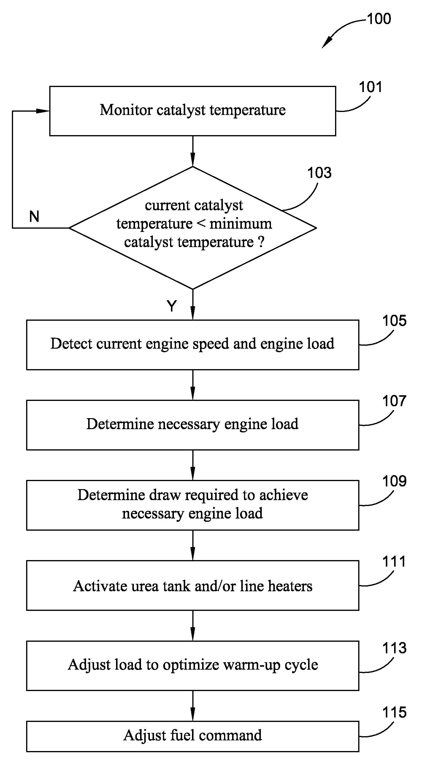
[0019]Referring to the drawings, FIG. 1 illustrates a control algorithm for regulating the temperature of an exhaust gas aftertreatment system in a motorized vehicle (not shown). Specifically, an improved method for accelerated warming of motor vehicle exhaust aftertreatment systems is shown in FIG. 1 in accordance with a preferred embodiment of the present invention, designated generally as 100. The method 100 preferably includes at least those steps shown in FIG. 1—i.e., steps 101-115. However, it is within the scope and spirit of the present invention to omit steps, include additional steps, and / or modify the order presented in FIG. 1. It should be further noted that the method 100 represents a single operation. As such, it is contemplated that the method 100 be applied in a systematic and repetitive manner, run in real-time to continuously adjust engine loading and optimize operation of the exhaust aftertreatment system.

[0020]The control algorithm 100 preferably resides in an en...


PUM


Abstract

The methods of the present invention are adapted to adjust engine loading during catalyst warm up to accelerate heating of the exhaust aftertreatment system and thereby decrease catalyst light-off times. According to a preferred embodiment of the present invention, the method includes: monitoring the current catalyst temperature; determining if the current catalyst temperature is less than a predetermined minimum catalyst temperature; and, if the current catalyst temperature is less than the predetermined minimum catalyst temperature, increasing the current engine load. The current engine load is increased by activating a reducing agent tank heating device and / or a reducing agent line heating device.

Description

TECHNICAL FIELD[0001]The present invention relates generally to exhaust aftertreatment systems. More particularly, the present invention is drawn to methods for accelerated warming of motor vehicle exhaust aftertreatment systems.BACKGROUND OF THE INVENTION[0002]Almost all conventional motorized vehicles, such as the modern-day automobile, include an exhaust aftertreatment system for mitigating the byproducts generated from operation of an internal combustion engine. Most exhaust aftertreatment systems include a catalytic converter for the reduction and oxidation of exhaust gas emissions, and a muffler assembly or similar device for attenuating noise generated by the exhaust emission process. The catalytic converter is normally placed between the engine exhaust manifold and the muffler of the automobile, but can also be integrated into the muffler assembly.[0003]Catalytic converters normally include a monolith substrate, generally of the ceramic honeycomb or stainless steel foil hone...

Claims


Application Information

Patent Timeline
20 May 2010
Publication
US20100122523A1
IPC
F01N9/00
CPC
F01N3/208; Y02T10/24; F01N2900/08; F01N2610/10; Y02T10/12; Y02A50/20
Inventors
VOSZ, ADAM