Oil control valve degradation detection and cleaning strategy

a technology of oil control valve and degradation detection, which is applied in the direction of mechanical equipment, machines/engines, transportation and packaging, etc., can solve the problems of degrading or possibly inhibiting the accurate control of oil control valve operation, degrading the operation of the oil control valve, and affecting the performance of the engine, so as to achieve the effect of improving engine performan

Active Publication Date: 2010-05-20
FORD GLOBAL TECH LLC
View PDF13 Cites 11 Cited by
  • Summary
  • Abstract
  • Description
  • Claims
  • Application Information

AI Technical Summary

Benefits of technology

[0001]Engines may use variable valve operation, such as variable cam timing, to improve engine performance. In one example, oil control valves, such as spool valves or solenoid valves, may be used to adjust the position (e.g., angle) of the cams via hydraulic actuation of a cam phaser. Therefore, the valve timing may be advanced or retarded depending on the desired valve operation.

Problems solved by technology

Degradation of an oil control valve may occur due to formation of particulates in the hydraulic fluid which may adhere to, or become trapped in, various parts of the valve.
The trapped particles may block flow channels, thereby degrading or possibly inhibiting accurate control of oil control valve operation.
This may degrade operation of the cams and therefore decrease the efficiency of the combustion process.
First, the available window of cleaning operation according to such approaches may be very small.
Moreover, the available window of operation may be further reduced in vehicles utilizing hybrid technology.

Method used


Image

  • Oil control valve degradation detection and cleaning strategy
  • Oil control valve degradation detection and cleaning strategy
  • Oil control valve degradation detection and cleaning strategy

Examples


Embodiment Construction

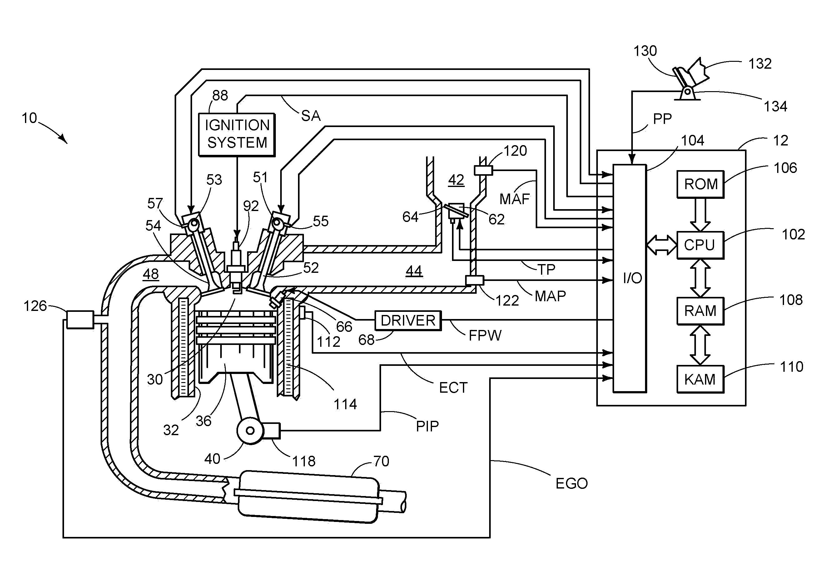
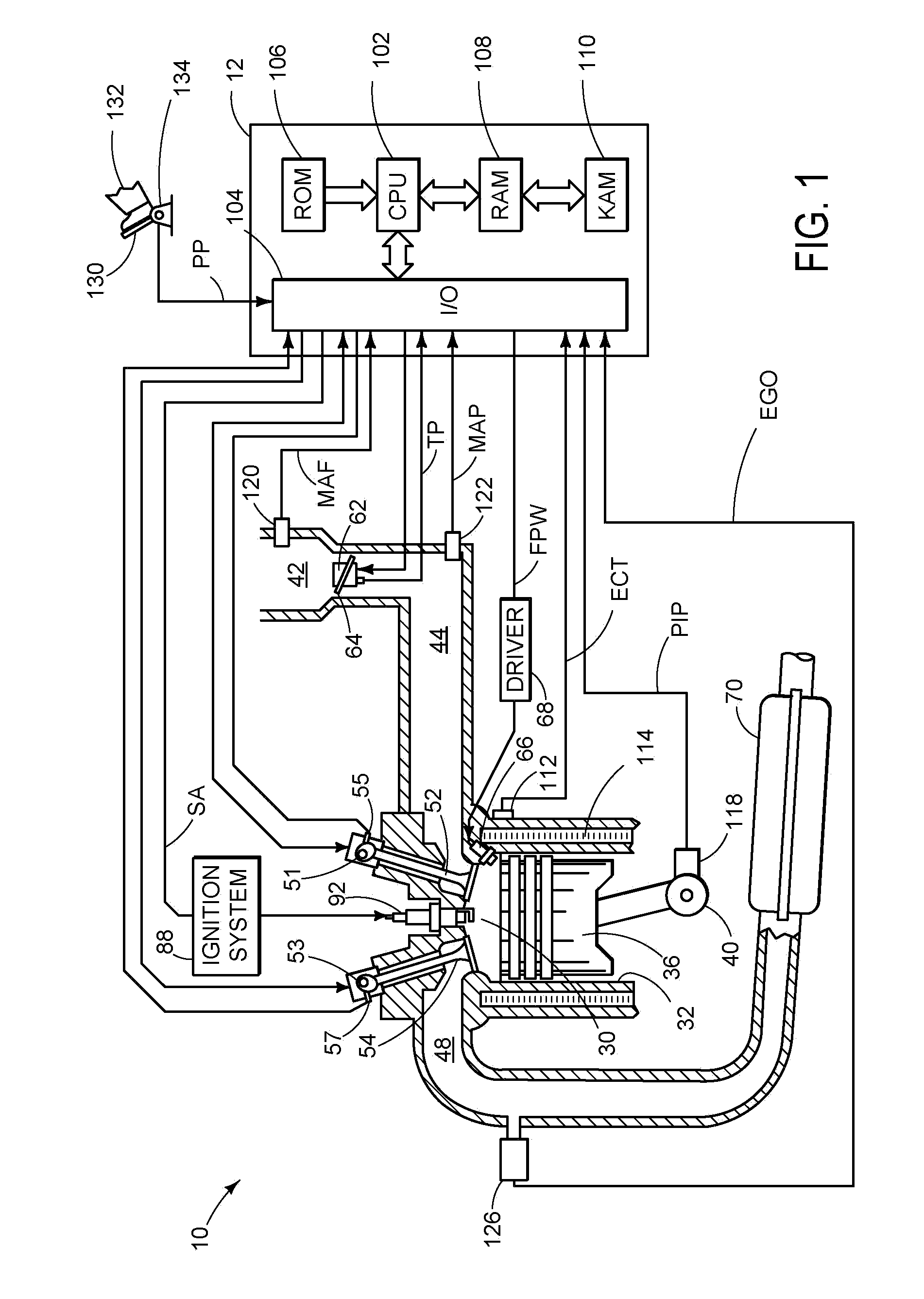
[0016]Internal combustion engines may use oil control valves, such as solenoid valves and variable valve operating systems to control actuation of the valve system. For example, oil control valves may be used in cam timing systems to control operation of a cam phaser. Due to potential for particulate and other debris to become lodged in the oil control valve, valve cleaning operations may be carried out.

[0017]In one example, a valve cleaning mode of operation is carried out during engine combustion operation and in coordination with modified feedback control of the cam actuation (e.g., cam timing). For example, during non-cleaning conditions, feedback control of cam timing via valve actuation may be carried out with parameters tuned for smooth valve control operation under a wide range of engine operating conditions. However, during select cleaning conditions, a modified feedback control operation, such as using high gain abrupt switching, or bang-bang, feedback control may be used....


PUM


Abstract

A method for operating an oil control valve coupled to a cam phaser configured to adjust a position of at least one cam between hard stops, the oil control valve included in an internal combustion engine having an intake valve and/or an exhaust valve controlled via the cam phaser. The method including operating the oil control valve responsive to cam position feedback information, the oil control valve adjusted in a first relationship based on the feedback information and operating the oil control valve in a cleaning mode during select combustion conditions by abruptly switching the oil control valve between two states responsive to the cam position feedback information. The oil control valve adjusted in a second relationship based on the feedback information, the second relationship including more abrupt adjustment than the first relationship.

Description

BACKGROUND AND SUMMARY[0001]Engines may use variable valve operation, such as variable cam timing, to improve engine performance. In one example, oil control valves, such as spool valves or solenoid valves, may be used to adjust the position (e.g., angle) of the cams via hydraulic actuation of a cam phaser. Therefore, the valve timing may be advanced or retarded depending on the desired valve operation.[0002]Degradation of an oil control valve may occur due to formation of particulates in the hydraulic fluid which may adhere to, or become trapped in, various parts of the valve. The trapped particles may block flow channels, thereby degrading or possibly inhibiting accurate control of oil control valve operation. This may degrade operation of the cams and therefore decrease the efficiency of the combustion process.[0003]Various control strategies have been designed to clean the oil control valve. Such control strategies may be implemented at specified time intervals during engine ope...

Claims


Application Information

Patent Timeline
Patent Type & Authority Applications(United States)
IPC IPC(8): B60K6/24F01L1/34F01L13/00
CPCF01L1/34F01L1/344F15B21/04F01L2001/34436F01L2800/00F01L2001/34426Y10S903/905
Inventor PADILLA, LAUREN ELIZABETHROLLINGER, JOHN ERIC
Owner FORD GLOBAL TECH LLC
Why Eureka
Try Eureka