Piezoelectric/electrostrictive ceramics composition, piezoelectric/electrostrictive ceramics sintered body, piezoelectric/electrostrictive element, manufacturing method of piezoelectric/electrostrictive ceramics composition, and manufacturing method of piezoelectric/electrostrictive element

a technology of piezoelectric/electrostrictive ceramics and manufacturing methods, which is applied in the direction of piezoelectric/electrostrictive transducers, device material selection, generators/motors, etc., can solve the problem of difficult to obtain and achieve a large electric field-induced strain and large displacement

Active Publication Date: 2010-05-20
NGK INSULATORS LTD +1
View PDF6 Cites 22 Cited by
  • Summary
  • Abstract
  • Description
  • Claims
  • Application Information

AI Technical Summary

Benefits of technology

[0018]According to the inventions of claims 1, 2 and 4, piezoelectric / electrostrictive ceramics with a large electric field-induced strain can be provided without performing an aging treatment.
[0019]According to the inventions of claims 3 and 5, a piezoelectric / electrostrictive element with a large displacement can be provided without performing an aging treatment.

Problems solved by technology

However, it is difficult to obtain a large electric field-induced strain, which is equivalent to that of a PZT-based leaded piezoelectric / electrostrictive material, only by the above method.

Method used


Image

  • Piezoelectric/electrostrictive ceramics composition, piezoelectric/electrostrictive ceramics sintered body, piezoelectric/electrostrictive element, manufacturing method of piezoelectric/electrostrictive ceramics composition, and manufacturing method of piezoelectric/electrostrictive element
  • Piezoelectric/electrostrictive ceramics composition, piezoelectric/electrostrictive ceramics sintered body, piezoelectric/electrostrictive element, manufacturing method of piezoelectric/electrostrictive ceramics composition, and manufacturing method of piezoelectric/electrostrictive element
  • Piezoelectric/electrostrictive ceramics composition, piezoelectric/electrostrictive ceramics sintered body, piezoelectric/electrostrictive element, manufacturing method of piezoelectric/electrostrictive ceramics composition, and manufacturing method of piezoelectric/electrostrictive element

Examples


first embodiment

1. First Embodiment

[0034]A first embodiment relates to piezoelectric / electrostrictive ceramics.

[0035]

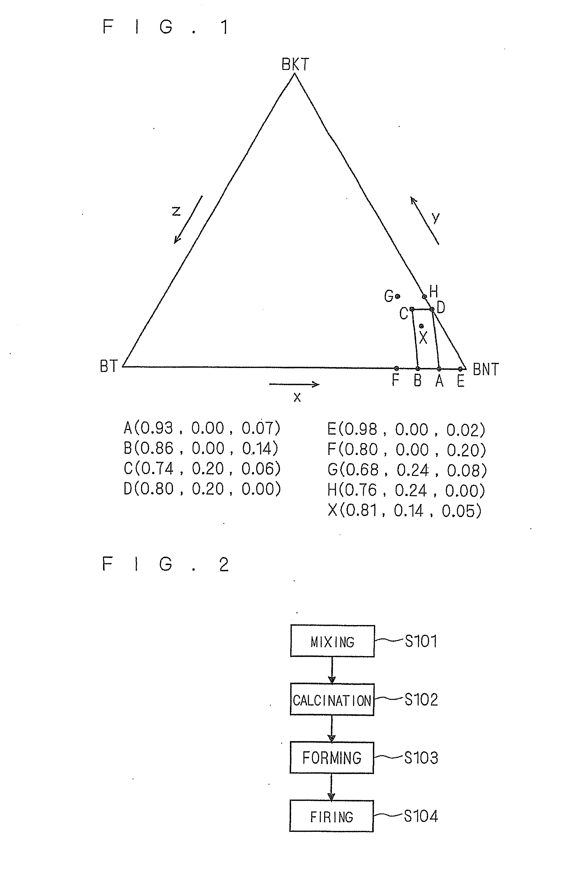
[0036]FIG. 1 is a diagram showing a desired composition range of the piezoelectric / electrostrictive ceramics according to the first embodiment. FIG. 1 is a three component-based ternary phase diagram of sodium bismuth titanate ((Bi1 / 2Na1 / 2)TiO3, hereinafter referred to as “BNT”), bismuth potassium titanate ((Bi1 / 2K1 / 2)TiO3, hereinafter referred to as “BKT”) and barium titanate ((BaTiO3, hereinafter referred to as “BT”).

[0037]The piezoelectric / electrostrictive ceramics according to the first embodiment have the composition represented by the general formula: xBNT-yBKT-zBT (x+y+z=1) wherein at least one kind among Bi (bismuth), Na (sodium) and K (potassium) as A-site elements is allowed to become deficient from stoichiometry in which a point (x, y, z) representing content ratios x, y and z of BNT, BKT and BT is within a range (also including a border line) of a quadrangle ABCD with a p...

second embodiment

2. Second Embodiment

[0064]The second embodiment relates to a piezoelectric / electrostrictive actuator 402 using the piezoelectric / electrostrictive ceramics of the first embodiment.

[0065]

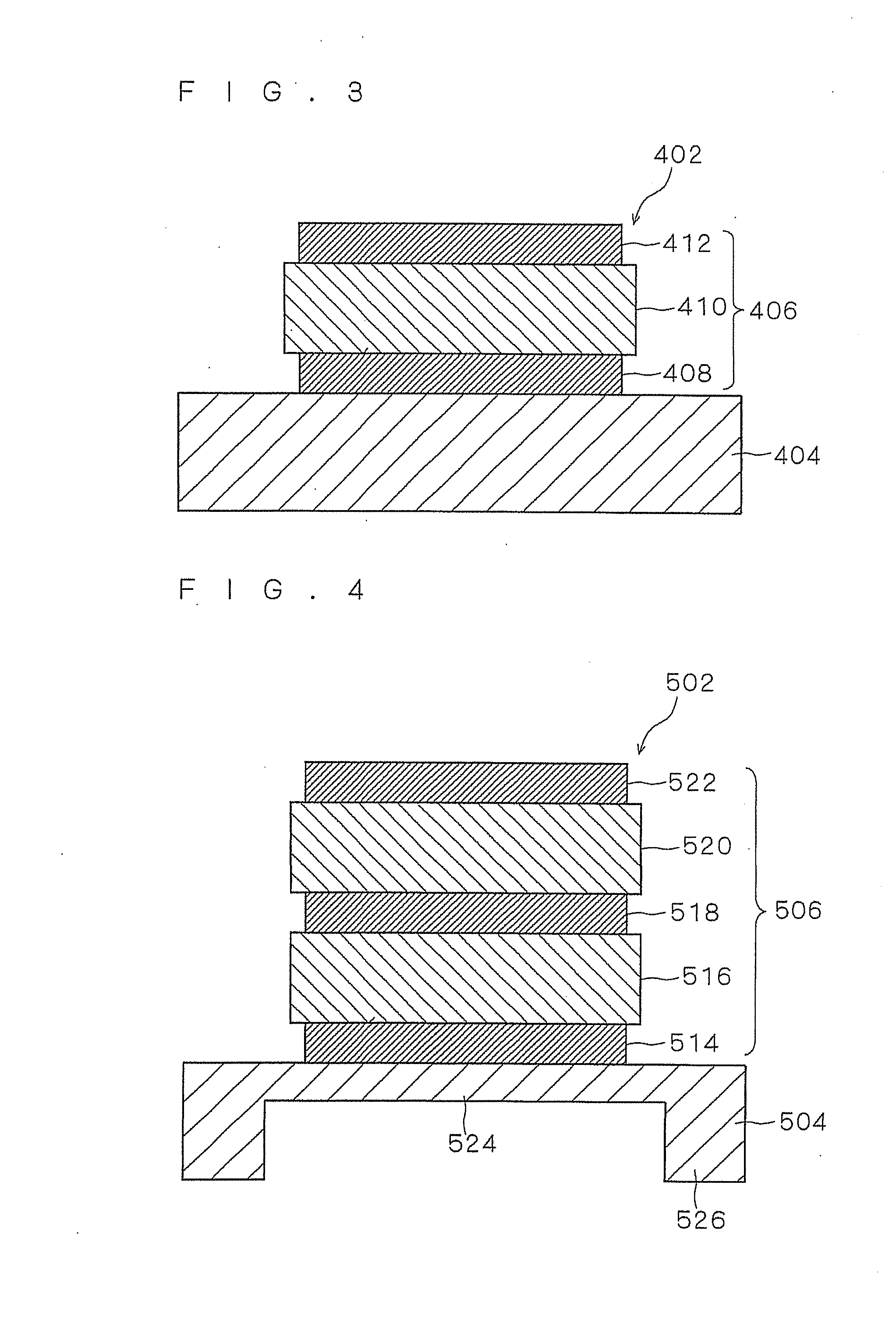
[0066]FIG. 3 is a schematic view of the piezoelectric / electrostrictive actuator 402 of the second embodiment. FIG. 3 is a sectional view of a single-layered piezoelectric / electrostrictive actuator 402.

[0067]As shown in FIG. 3, the piezoelectric / electrostrictive actuator 402 has a structure in which an electrode film 408, a piezoelectric / electrostrictive film 410 and an electrode film 412 are laminated in this order on a top surface of a substrate 404. The electrode films 408 and 412 on both main surfaces of the piezoelectric / electrostrictive film 410 face each other across the piezoelectric / electrostrictive film 410. A laminate 406 in which the electrode film 408, the piezoelectric / electrostrictive film 410 and the electrode film 412 are laminated is fixed to the substrate 404.

[0068]“Fixation” as used...

third embodiment

3. Third Embodiment

[0088]The third embodiment relates to a structure of a piezoelectric / electrostrictive actuator 502 which can be employed in place of the structure of the piezoelectric / electrostrictive actuator 402 of the second embodiment.

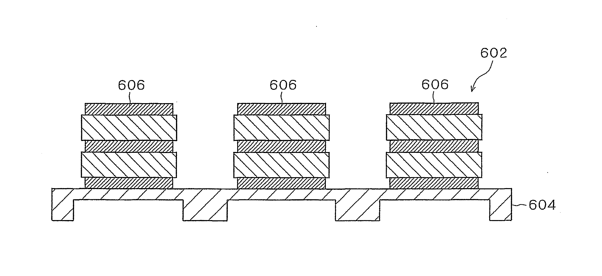
[0089]FIG. 4 is a schematic view of the piezoelectric / electrostrictive actuator 502 of the third embodiment. FIG. 4 is a sectional view of a multi-layered piezoelectric / electrostrictive actuator 502.

[0090]As shown in FIG. 4, the piezoelectric / electrostrictive actuator 502 has a structure in which an electrode film 514, a piezoelectric / electrostrictive film 516, an electrode film 518, a piezoelectric / electrostrictive film 520 and an electrode film 522 are laminated in this order on a top surface of a substrate 504. The electrode films 514 and 518 on both main surfaces of the piezoelectric / electrostrictive film 516 face each other across the piezoelectric / electrostrictive film 516, while the electrode films 518 and 522 on both main surfaces of the...


PUM

PropertyMeasurementUnit
piezoelectric/electrostrictiveaaaaaaaaaa
compositionaaaaaaaaaa
displacementaaaaaaaaaa

Abstract

[Object] To provide piezoelectric/electrostrictive ceramics and a piezoelectric/electrostrictive element with a large electric field-induced strain without performing an aging treatment.
[Solving Means] Piezoelectric/electrostrictive ceramics have the composition represented by the general formula: xBNT-yBKT-zBT (x+y+z=1) wherein at least one kind among A-site elements are allowed to become deficient from stoichiometry in which a point (x, y, z) representing content ratios x, y and z of (Bi1/2Na1/2)TiO3, (Bi1/2K1/2)TiO3 and BaTiO3 is within a range (also including a border line) of a quadrangle ABCD with a point A, a point B, a point C and a point D as vertices in a ternary phase diagram. Vacancies are formed in an A-site of a perovskite structure by allowing the A-site elements to become deficient from stoichiometry. An amount of A-site vacancies becomes at least 2 mol % to at most 6 mol %.

Description

TECHNICAL FIELD[0001]The present invention relates to a sodium bismuth titanate-based piezoelectric / electrostrictive ceramic composition and a technology in relation to the same.BACKGROUND ART[0002]A piezoelectric / electrostrictive actuator has such an advantage that a displacement can be accurately controlled in a submicron order. Particularly, a piezoelectric / electrostrictive actuator using a sintered body of piezoelectric / electrostrictive ceramics as a piezoelectric / electrostrictive body can accurately control a displacement, and also has advantages such as high electromechanical conversion efficiency, a large generation force, a high response speed, high durability and less power consumption. Therefore, the piezoelectric / electrostrictive actuator using the sintered body of piezoelectric / electrostrictive ceramics as the piezoelectric / electrostrictive body is employed as a head of an inkjet printer, an injector of a diesel engine and so on utilizing these advantages.[0003]As the si...

Claims


Application Information

Patent Timeline
Patent Type & Authority Applications(United States)
IPC IPC(8): H01L41/047H01L41/187H01L41/24C04B35/462H01L41/083H01L41/09H01L41/18H01L41/22H01L41/257H01L41/39H01L41/43H03H9/17
CPCH01L41/083H01L41/1878H01L41/0973Y10T29/42H01L41/43H01L41/273H01L41/314H10N30/50H10N30/2047H10N30/8561H10N30/053H10N30/074H10N30/097
Inventor YAMAGUCHI, HIROFUMIOZAWA, SHUICHINOGUCHI, YUJIMIYAYAMA, MASARU
Owner NGK INSULATORS LTD
Why Eureka
Try Eureka