Constant-temperature type crystal oscillator
- Summary
- Abstract
- Description
- Claims
- Application Information
AI Technical Summary
Benefits of technology
Problems solved by technology
Method used
Image

Examples
first embodiment
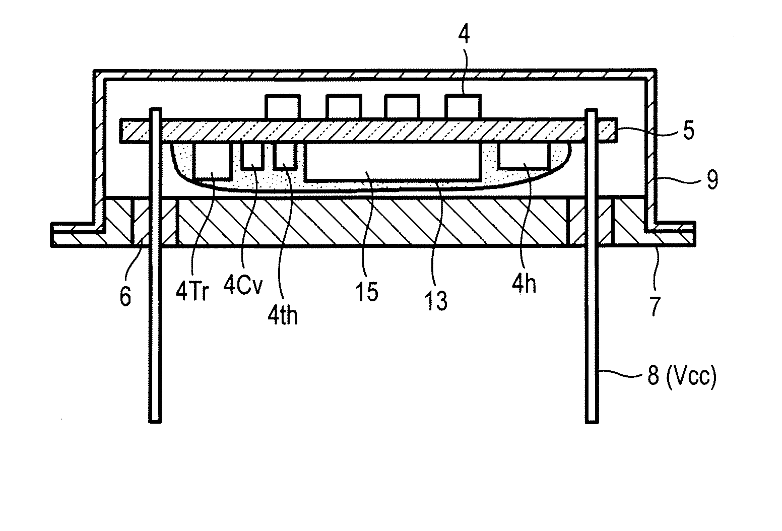
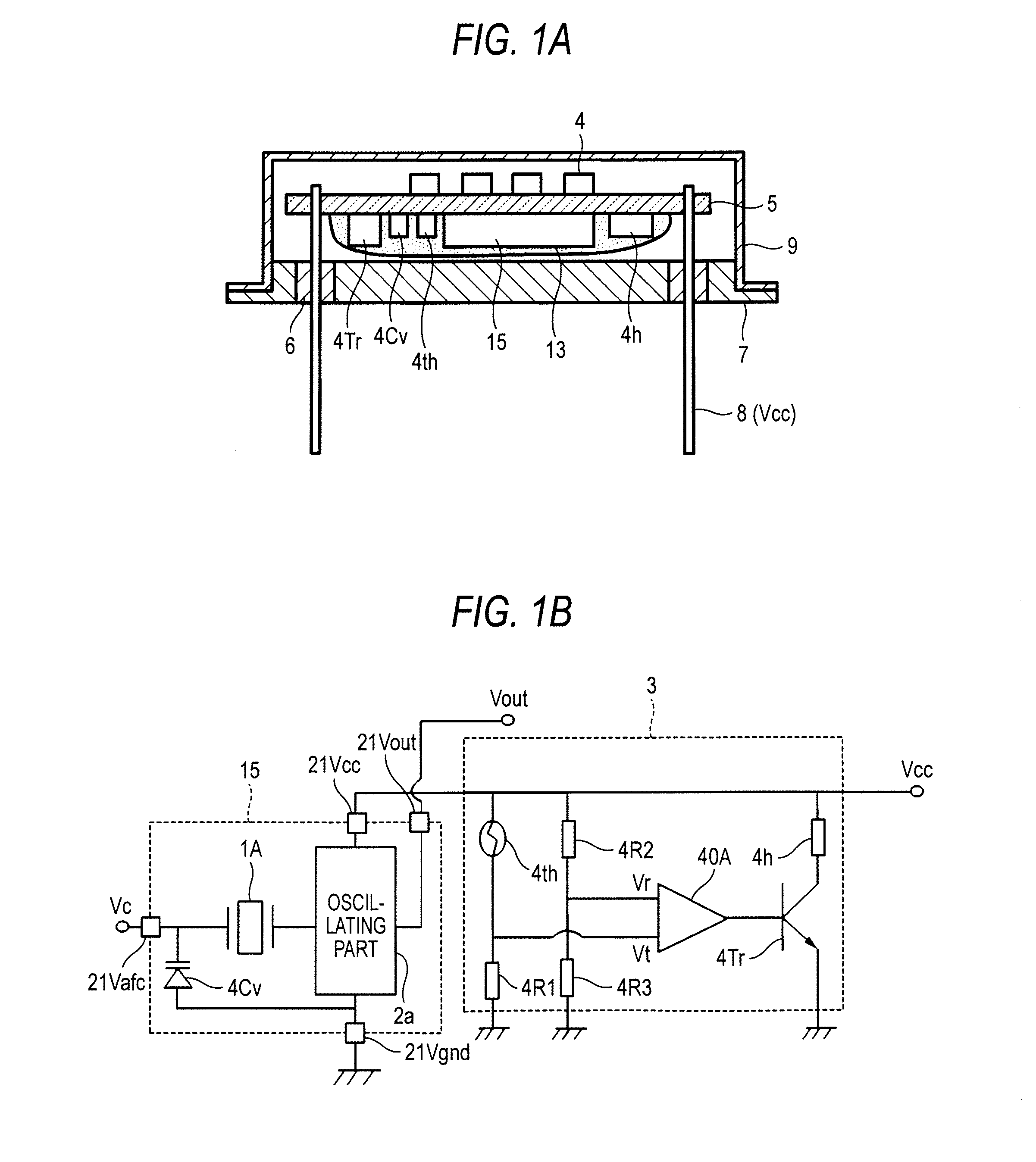
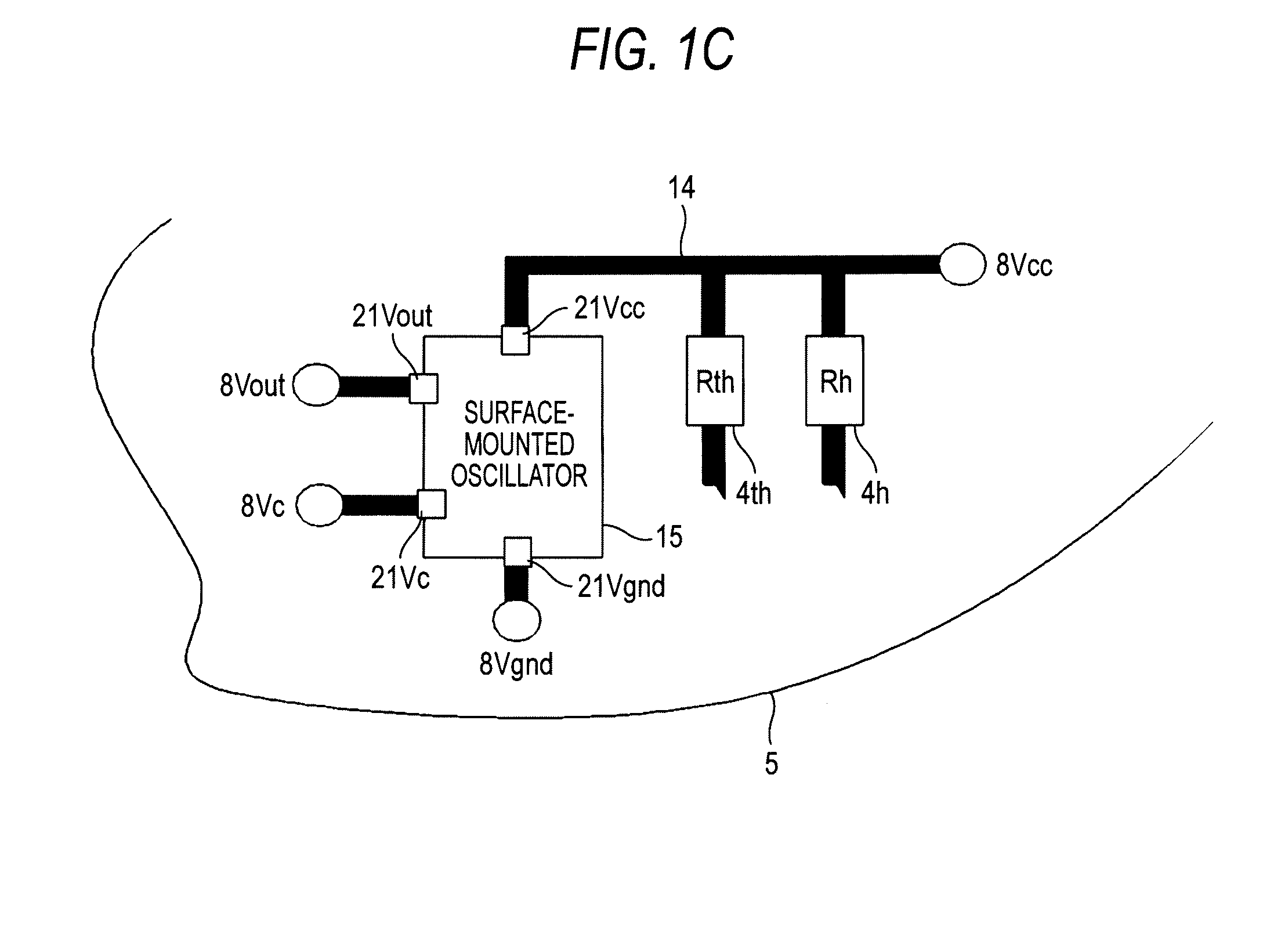
[0042]FIGS. 1A to 1C are diagrams of a constant-temperature type oscillator according to a first embodiment of the invention. FIG. 1A is a cross-sectional view thereof, FIG. 1B is a circuit diagram thereof, and FIG. 1C is a schematic diagram showing a connection between circuit elements and an electrically-conducting path therein. Incidentally, portions which are the same as those in the related example are denoted by the same symbols, and descriptions thereof will be simplified or omitted.
[0043]The constant-temperature type oscillator is configured such that a surface-mounted oscillator 15 in place of the surface-mounted unit 1 in the related example and the circuit elements 4 which are the same as those in the related example are installed on the circuit substrate 5, the circuit substrate 5 is held with lead wires 8 (second mounting terminals) of the base for oscillator 7, and a cover 9 covers these components. The lead wires 8 include a second power source terminal 8 (Vcc), an ou...
second embodiment
[0051]FIG. 3 is a circuit diagram of a constant-temperature type oscillator according to a second embodiment of the invention. Incidentally, descriptions of the same portions as those in the first embodiment will be omitted.
[0052]In the second embodiment, in the same way as in the related example, a constant-voltage circuit 24 is provided to the power source line between one end of the heating resistor 4h of the temperature control circuit 3 and one end of the resistor 4R2 forming the reference voltage Vr so as to eliminate noise contained in the power source Vcc and to improve an output from the oscillator circuit. In this case, the one end of the first power source terminal 21 (Vcc) of the surface-mounted oscillator 15 and the one end of the temperature sensor 4th are connected via the electrically-conducting path 14.
[0053]Therefore, the case main body 16 (the crystal unit in which the crystal element 1A is housed) and the temperature sensor 4th are thermally coupled via the elect...
third embodiment
[0054]FIG. 4 is a schematic diagram of specifically a surface-mounted oscillator for explanation of a constant-temperature type oscillator of a third embodiment of the invention. Incidentally, descriptions of the same portions as those in the above embodiment will be omitted.
[0055]In the third embodiment, the surface-mounted oscillator 15 is formed as a temperature compensated type, a so-called, TCXO. That is, in the IC chip 17, a temperature compensating mechanism having not only the oscillating part 2a, but also at least a temperature sensor (for example, a linear resistor) is integrated, to apply a temperature compensated voltage to the voltage-controlled capacitive element 4Cv. In this case, the temperature compensated voltage is synthesized with a control voltage Vc from the control terminal 21 (Vc) by an adder 25 and is applied to the voltage-controlled capacitive element 4Cv. In such an oscillator, because its frequency-temperature characteristic temperature-compensated in ad...
PUM
 Abstract
Description
Claims
Application Information
 - Generate Ideas
- Intellectual Property
- Life Sciences
- Materials
- Tech Scout
- Unparalleled Data Quality
- Higher Quality Content
- 60% Fewer Hallucinations
Browse by: Latest US Patents, China's latest patents, Technical Efficacy Thesaurus, Application Domain, Technology Topic, Popular Technical Reports.
© 2025 PatSnap. All rights reserved.Legal|Privacy policy|Modern Slavery Act Transparency Statement|Sitemap|About US| Contact US: help@patsnap.com