

Zoom lens and image pickup device
a pickup device and zoom lens technology, applied in the field of zoom lens and image pickup device, can solve the problems of large amount of aberration correction assigned to each lens forming the second lens group, insufficient aberration correction, and hindering miniaturization, so as to improve mass productivity and improve performan
- Summary
- Abstract
- Description
- Claims
- Application Information
AI Technical Summary
Benefits of technology
Problems solved by technology
Method used
Image

Examples
first embodiment
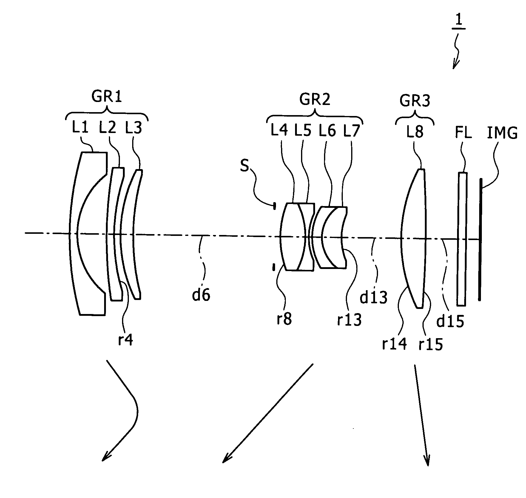
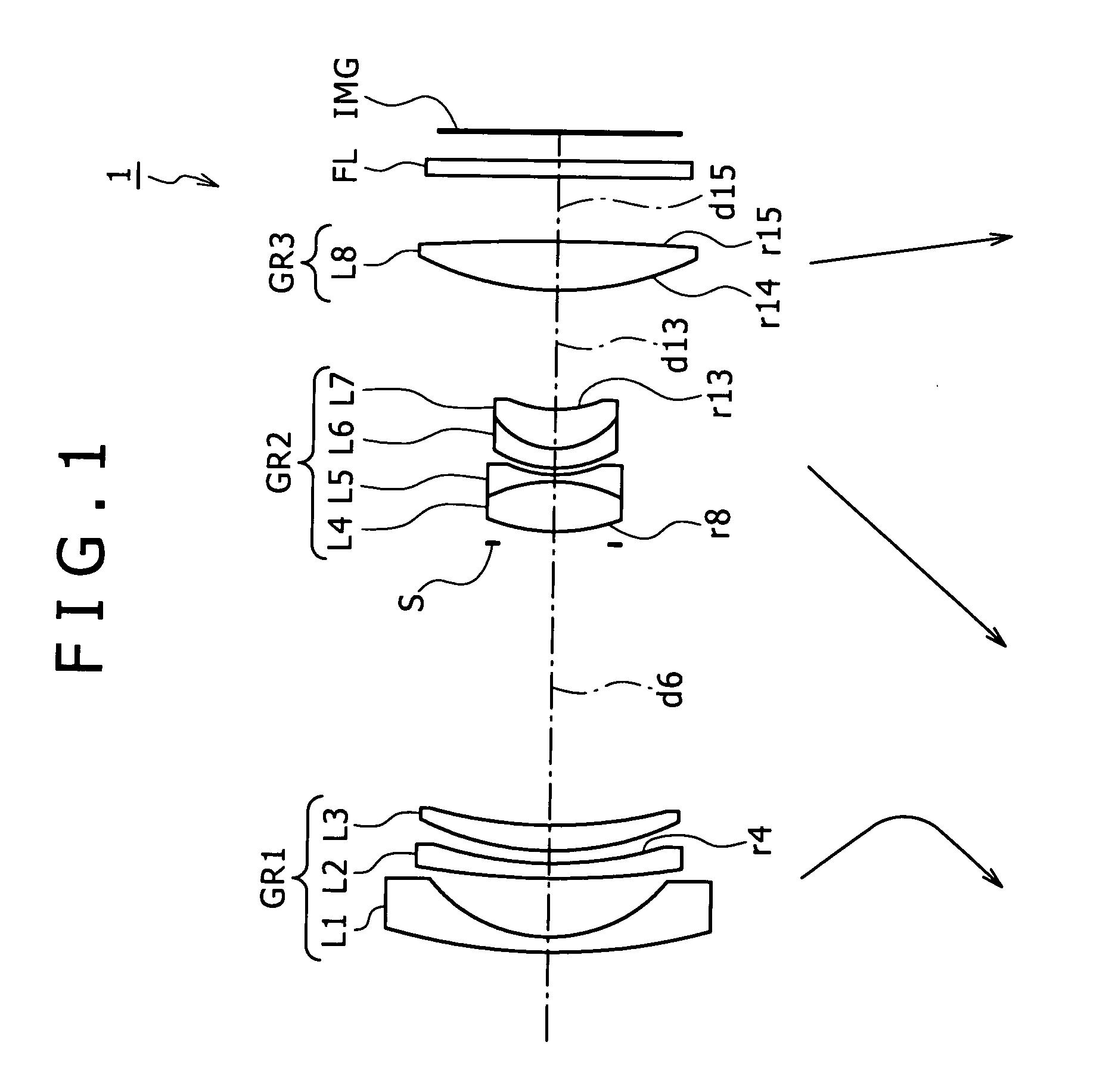
[0073]FIG. 1 is a diagram showing the lens configuration of a zoom lens 1 according to the present invention.
[0074]The zoom lens 1 according to the first embodiment has eight lenses, as shown in FIG. 1.
[0075]The first lens group GR1 is formed by arranging a first lens L1 as a negative meniscus lens having a convex surface facing the object side, a second lens L2 as a negative meniscus lens having a surface on the image side formed as an aspheric surface and having a convex surface facing the object side, and a third lens L3 as a positive meniscus lens having a convex surface facing the object side in order from the object side to the image side.
[0076]A second lens group GR2 is formed by two cemented lenses. The cemented lens disposed on the object side is formed by a fourth lens L4 as a biconvex lens having a surface on the object side formed as an aspheric surface and a fifth lens L5 as a biconcave lens. The cemented lens disposed on the image side is formed by a sixth lens L6 as a...
second embodiment
[0087]FIG. 5 is a diagram showing the lens configuration of a zoom lens 2 according to the present invention.
[0088]The zoom lens 2 according to the second embodiment has eight lenses, as shown in FIG. 5.
[0089]The first lens group GR1 is formed by arranging a first lens L1 as a negative meniscus lens having a convex surface facing the object side, a second lens L2 as a negative meniscus lens having a surface on the image side formed as an aspheric surface and having a convex surface facing the object side, and a third lens L3 as a positive meniscus lens having a convex surface facing the object side in order from the object side to the image side.
[0090]The aspheric surface of the second lens L2 is formed by thinly coating a resin.
[0091]A second lens group GR2 is formed by arranging a fourth lens L4 as a positive meniscus lens having a surface on the object side formed as an aspheric surface and having a convex surface facing the object side, a cemented lens, and a seventh lens L7 as ...
third embodiment
[0101]FIG. 9 is a diagram showing the lens configuration of a zoom lens 3 according to the present invention.
[0102]The zoom lens 3 according to the third embodiment has eight lenses, as shown in FIG. 9.
[0103]The first lens group GR1 is formed by arranging a first lens L1 as a negative meniscus lens having a convex surface facing the object side, a second lens L2 as a negative meniscus lens having a surface on the image side formed as an aspheric surface and having a convex surface facing the object side, and a third lens L3 as a positive meniscus lens having a convex surface facing the object side in order from the object side to the image side.
[0104]A second lens group GR2 is formed by arranging a cemented lens, a sixth lens L6 as a negative meniscus lens having a concave surface facing the object side, and a seventh lens L7 as a biconvex lens in order from the object side to the image side. The cemented lens is formed by joining together a fourth lens L4 as a biconvex lens having ...
PUM
 Abstract
Description
Claims
Application Information