

Roof ridge wind turbine
a wind turbine and roof technology, applied in the direction of wind motors with parallel air flow, wind energy generation, perpendicular air flow, etc., can solve the problems of large blades, noise generation, and air pressure imparted to the roof structure, and achieve the effect of increasing the wind speed, reducing the air pressure, and increasing the velocity
Inactive Publication Date: 2010-05-27
TURBOROOF
View PDF4 Cites 29 Cited by
- Summary
- Abstract
- Description
- Claims
- Application Information
AI Technical Summary
Benefits of technology
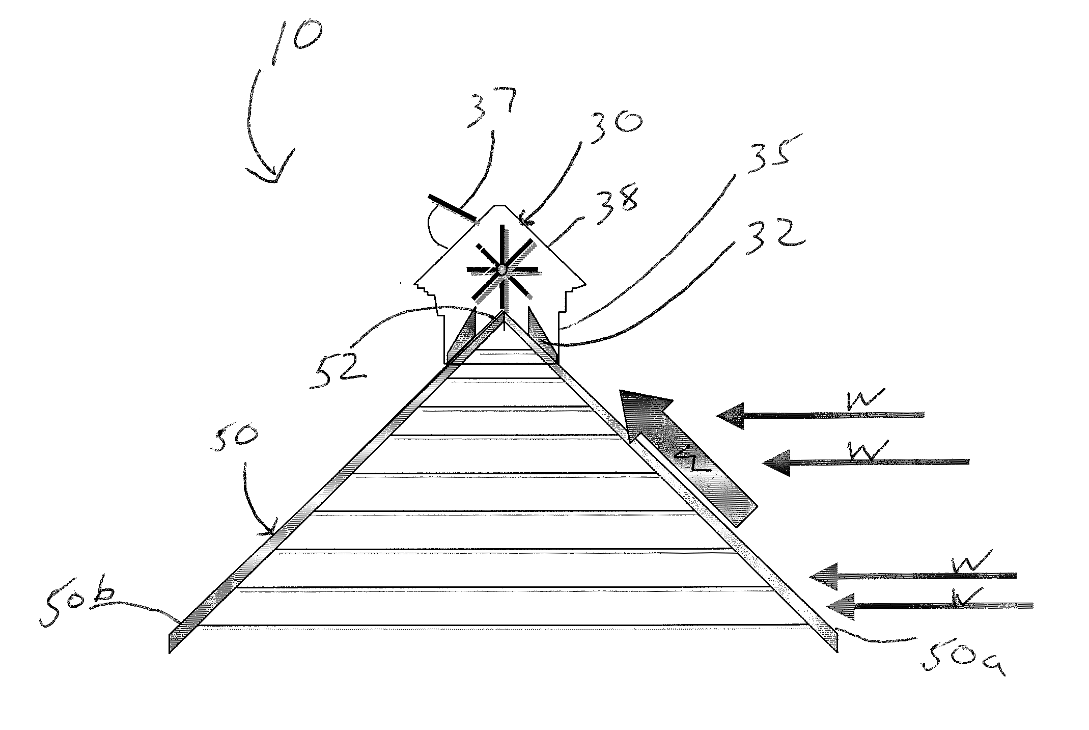
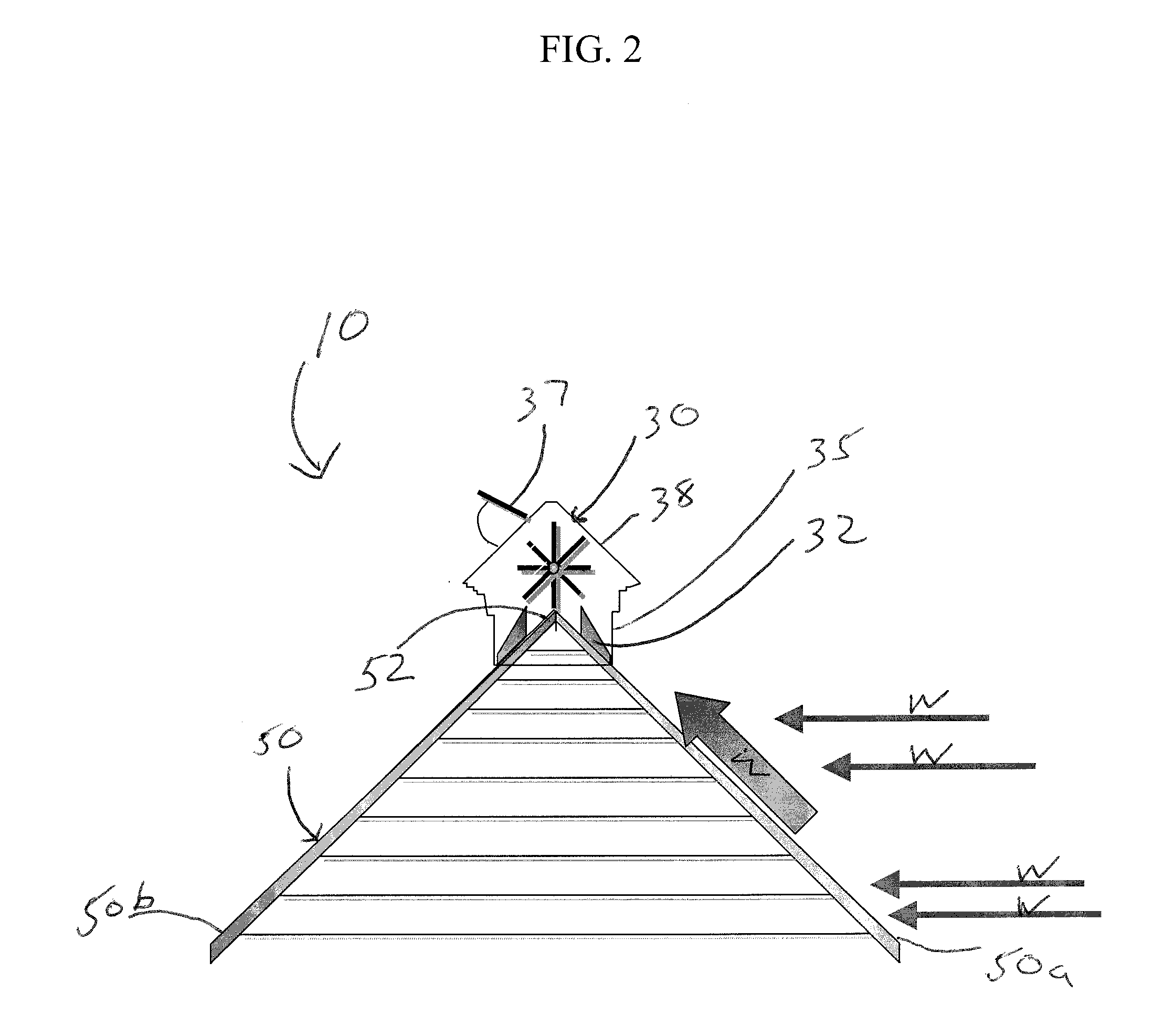
[0008]The present invention disclosure describes wind energy harvesting systems that can be mounted along the ridge of a gabled roof to take full advantage of the well known “roof effect” whereby the wind impacts the surface of the sloped face of the gabled roof and deflects the airflow upwards towards the ridge, thus multiplying the wind speed. This effect is similar to air increasing in velocity over a wing, which lowers the air pressure above the wing according to Bernoulli's equation and thus provides lift to the wing. This effect also causes roofs to completely lift off houses in a hurricane.
[0009]The present invention comprises a wind turbine device enclosed within a low silhouette structure to hide the device from view and to make it visually appealing. The enclosure also prevents harm to birds and prevents snow accumulation on the device in cold localities. The enclosure also serves to capture the airflow before it encounters the stagnation point now known to occur at the peak of a gabled roof.
[0010]The system can be retrofitted to an existing sloped roof where it is mounted directly to the roof or it can be partially recessed into the roof of a new construction building to further improve wind energy capture and visual appeal.
Problems solved by technology
The reasons for this are many but typically include the unsightliness of large blade wind turbines, the noise generated by these wind turbines, the vibration imparted to the roof structure and the hazards to birds.
These systems have serious flaws in the positioning of the wind turbine and in the design of the airflow channel, which significantly degrades potential performance.
This effect also causes roofs to completely lift off houses in a hurricane.
Method used
View moreImage
Smart ImageViewing Examples

Examples
example
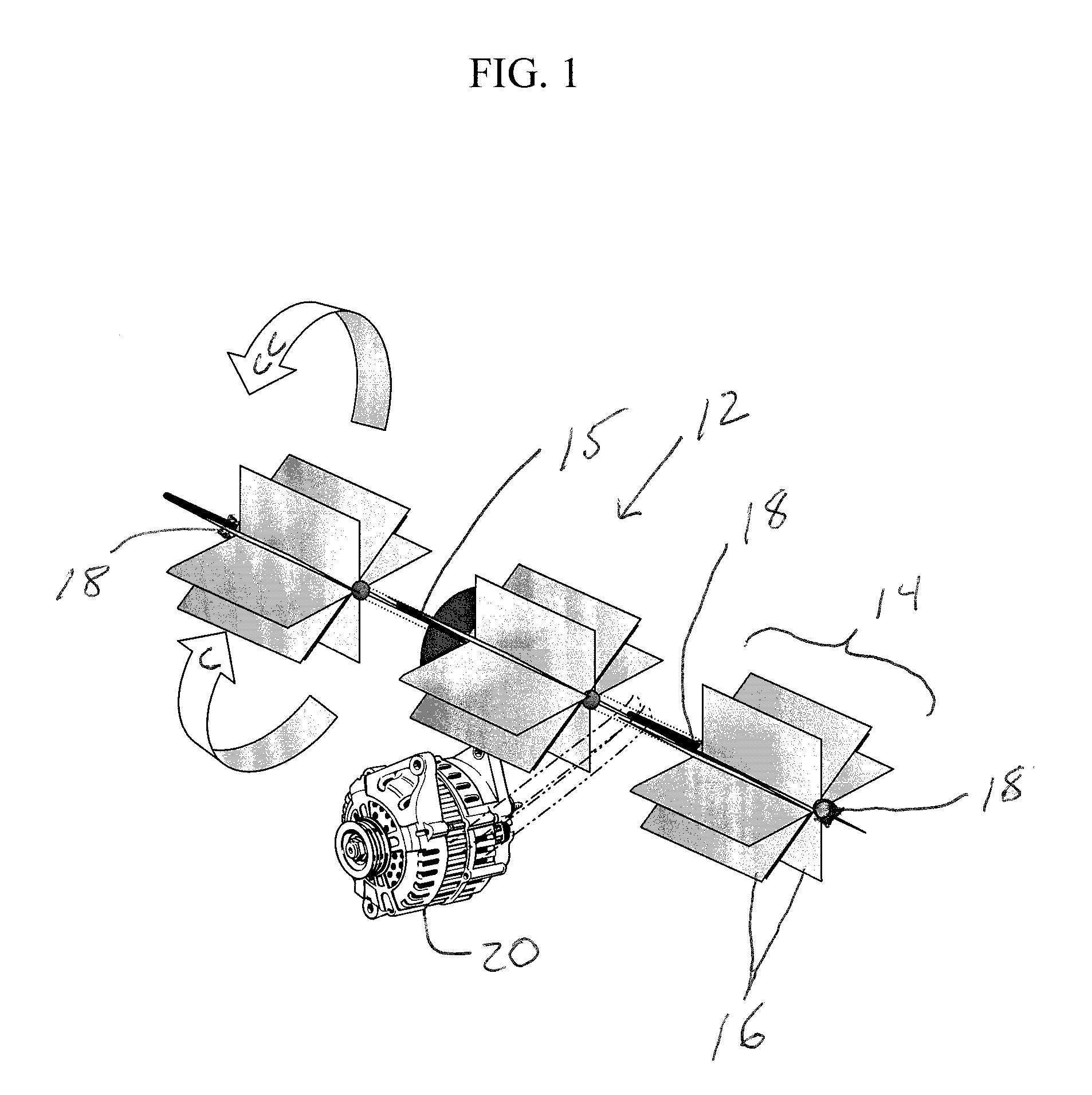
[0029]Table 1, below shows the calculated wind energy available utilizing the roof ridge wind turbine. The performance of a 20-foot long roof ridge wind turbine with one-foot wide blades is compared to a tower mounted five-foot diameter propeller type wind turbine at a light wind speed of 10 miles per hour.
TABLE 1Wind Turbine comparisonWindRoofSpeed,Swept Area,EffectWind EnergyMiles / hourSq. metersFactorAvailable, Watts5 ft diameter101.80100propeller typeRoof ridge type101.81100Roof ridge type101.81.5344Roof ridge type101.82816Roof ridge type101.82.51595
Login to View More PUM
 Abstract
Disclosed are systems and method that generally relate to the capture of wind energy by small wind turbines mounted on buildings with gabled roofs. Wind energy harnessing system for gabled roof buildings having a roof ridge including a low silhouette visually appealing enclosure mounted along the roof ridge of a building and extending down both sides of the roof forming the ridge. The enclosure includes airflow guides defined by columns extending down a length of both sides of the building roof forming sidewalls and a roof formed of pivoting louvers above the columns. A paddle-wheel type wind turbine consists of a multiple-bladed cylindrical shaft that contacts the wind and provides rotational work mounted within the enclosure and a generator connected to the wind turbine for converting the rotational work from the wind turbine to electrical energy. The enclosure for the wind turbine functions to capture wind and directs the airflow via the airflow guides before it reaches the ridge.
Description
CROSS REFERENCE TO RELATED APPLICATION[0001]This application claims the benefit of U.S. Provisional Patent Application Ser. No. 61 / 105,096, filed Nov. 24, 2008, entitled “ROOF RIDGE WIND TURBINE”.TECHNICAL FIELD[0002]The present invention generally relates to small wind turbines. More particularly, the invention discloses systems that can be mounted along the ridge of a gabled roof building to capture wind energy and benefit from the wind deflected to the ridge by the sloped face of the roof.BACKGROUND INFORMATION[0003]Energy capture from the wind is not only a pollution-free resource, but also a means to help reduce dependence on foreign oil. Significant effort has been undertaken by government and industry on large wind turbine systems because of their intrinsic high efficiency. Considerably less attention has been focused on smaller wind systems that can be placed on the roofs of buildings. The reasons for this are many but typically include the unsightliness of large blade wind ...
Claims
Login to View More Application Information
Patent Timeline
 Patent Type & AuthorityApplications(United States)
IPC IPC(8): E04D13/18E04B1/38F03D3/04F03D9/00
CPCF03D3/002F05B2240/911Y02E10/74Y02E10/728Y02B10/30
InventorPAGGI, RAYMOND E.
OwnerTURBOROOF