Motor driving circuit

a technology of driving circuit and motor, which is applied in the direction of motor/generator/converter stopper, electronic commutator, dynamo-electric converter control, etc., can solve the problems of long recovery period of transistors, reduced power conversion efficiency of inverters, and substantial power loss, and achieves simple configuration

Active Publication Date: 2010-05-27
PANASONIC CORP
View PDF29 Cites 36 Cited by
  • Summary
  • Abstract
  • Description
  • Claims
  • Application Information

AI Technical Summary

Benefits of technology

[0015]With the disclosed motor driving circuit, it is possible to implement an inverter withou...

Problems solved by technology

A recovery current is a power that is unnecessary for driving a motor, and is consumed as heat by an inverter circuit, thereby being a cause for a decrease in the power conversion efficiency of the inverter.
Howe...

Method used


Image

  • Motor driving circuit
  • Motor driving circuit
  • Motor driving circuit

Examples


first embodiment

[0117]A first embodiment of the present invention will now be described with reference to the drawings.

[0118](1) Configuration of Inverter Circuit

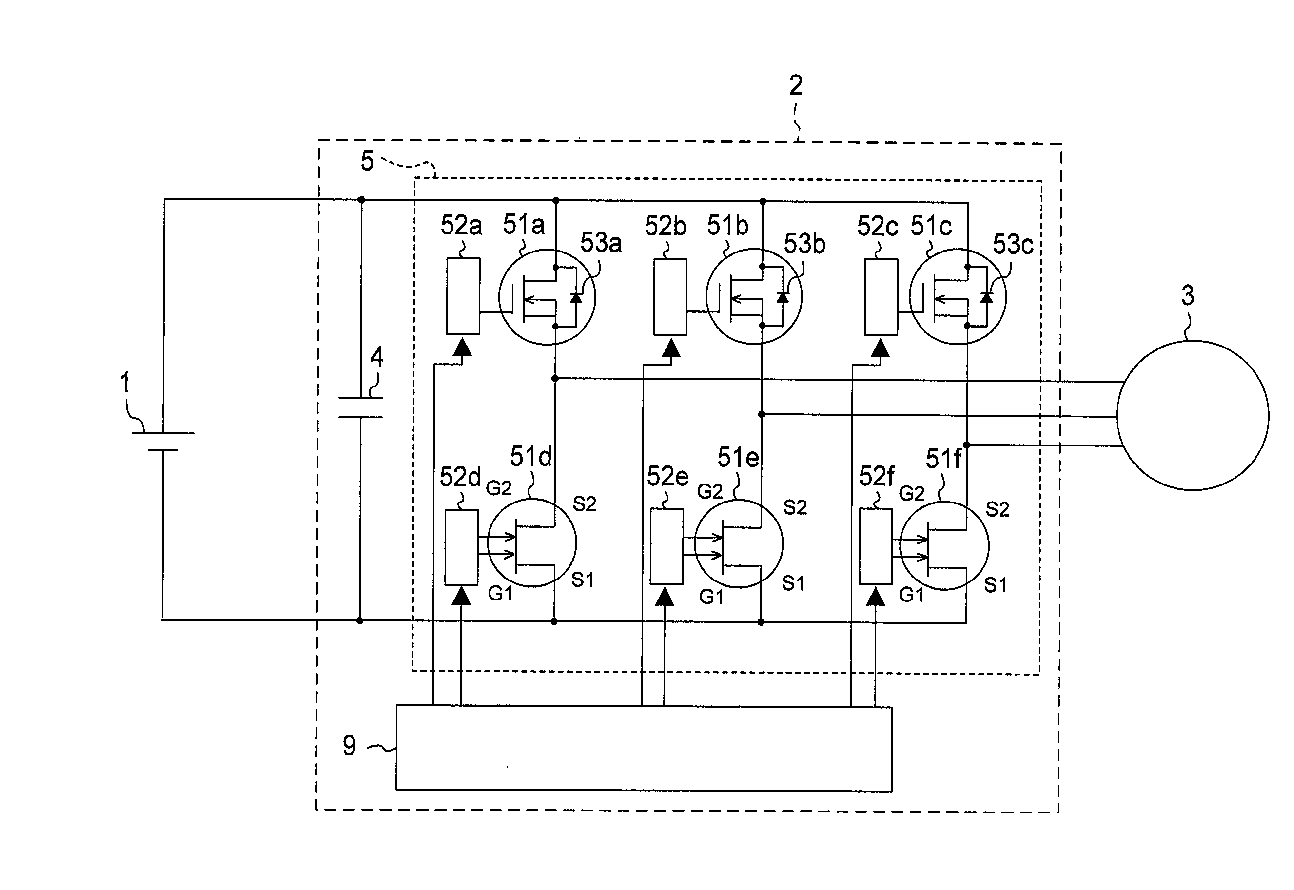
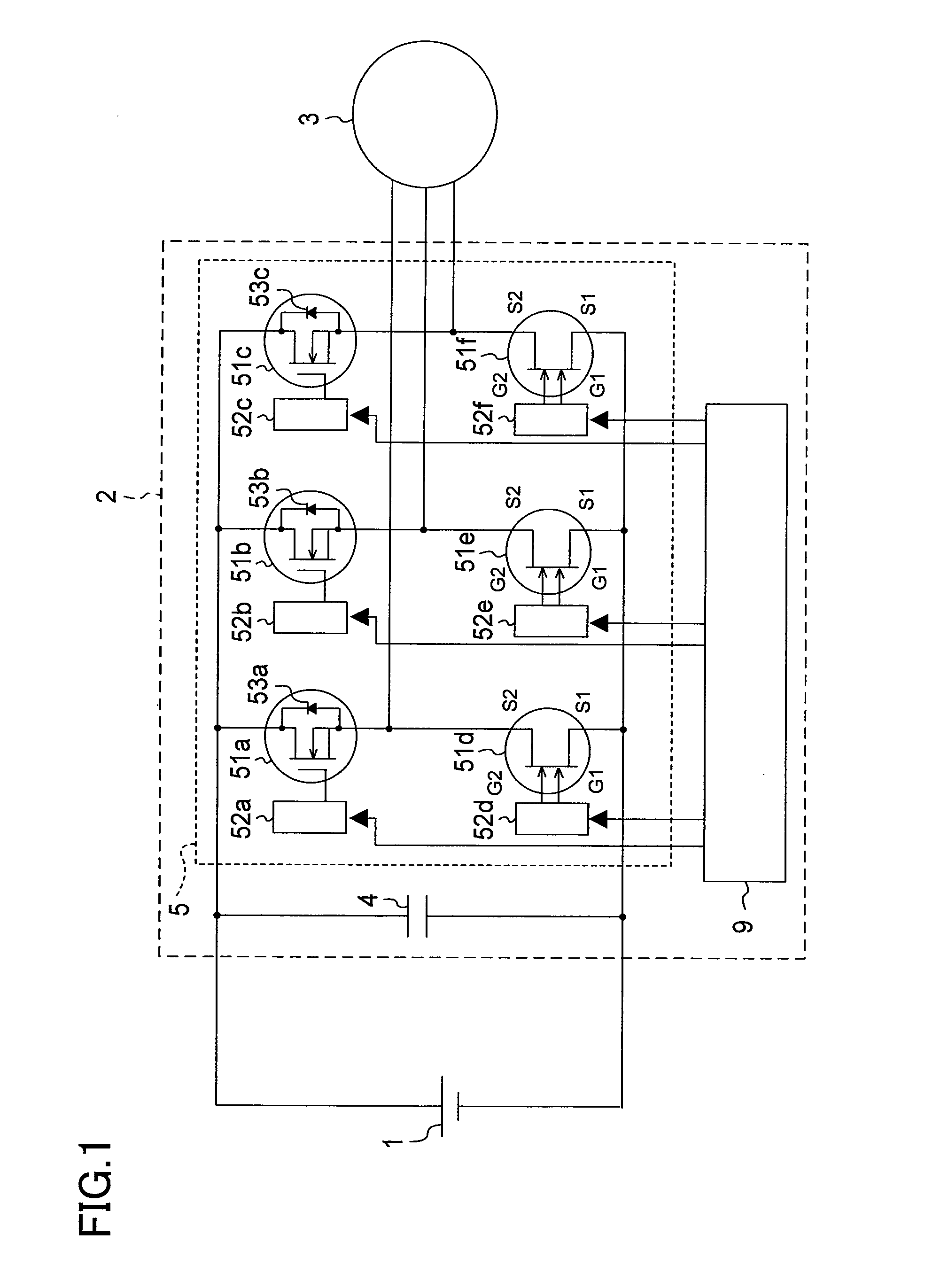
[0119]A DC motor driving circuit of the present embodiment will be described with reference to the drawings. FIG. 1 shows a circuit configuration of a three-phase brushless DC motor driving circuit. As shown in FIG. 1, a motor driving circuit 2 of the first embodiment receives a DC power supplied from a DC power source 1 to drive a three-phase brushless DC motor, which is a permanent magnet synchronous motor.

[0120]The motor driving circuit 2 includes a smoothing capacitor 4, a three-phase inverter circuit 5, and a gate controller 9.

[0121]A three-phase brushless DC motor 3 includes a U-phase coil, a V-phase coil and a W-phase coil connected together in a start connection (or a delta connection), and the rotor is equipped with a predetermined number of pairs of field magnets.

[0122]The three-phase inverter circuit 5 is a DC-AC conversion circ...

second embodiment

[0193]A second embodiment of the present invention will now be described with reference to the drawings.

[0194](1) Configuration of Motor Driving Circuit

[0195]A circuit in a motor driving circuit of the present embodiment will now be described with reference to FIG. 10. FIG. 10 is a diagram showing a motor driving circuit for driving a three-phase brushless DC motor. As shown in FIG. 10, a motor driving circuit 2 of the second embodiment receives DC power supplied from a DC power source 1 to drive a three-phase brushless DC motor, which is a permanent magnet synchronous motor.

[0196]The motor driving circuit 2 includes a smoothing capacitor 4, a three-phase inverter circuit 8, and a gate controller 9.

[0197]A three-phase brushless DC motor 3 includes a U-phase coil, a V-phase coil and a W-phase coil connected together in a start connection (or a delta connection), and the rotor is equipped with a predetermined number of pairs of field magnets.

[0198]The three-phase inverter circuit 8 is...


PUM


Abstract

A motor driving circuit includes a three-phase inverter circuit 8, including three upper-arm switching elements 56a to 56c for driving upper arms of different phases of a three-phase motor 3, and three lower-arm switching elements 56d to 56f for driving lower arms of different phases. At least one of the upper-arm switching elements 56a to 56c and the lower-arm switching elements 56d to 56f is a semiconductor element that performs a diode operation. The diode operation is an operation in which a voltage less than or equal to a threshold voltage of a gate electrode G is applied to the gate electrode G with reference to a potential of a first ohmic electrode S, thereby conducting a current flow from the first ohmic electrode S to a second ohmic electrode D and blocking a current flow from the second ohmic electrode D to the first ohmic electrode S.

Description

TECHNICAL FIELD[0001]The present invention relates to a motor driving circuit for controlling a three-phase motor by an inverter control.BACKGROUND ART[0002]When a three-phase brushless DC motor is controlled by an inverter control, upper-arm switching elements and lower-arm switching elements of a three-phase inverter circuit are switched around so as to convert a DC power to a three-phase AC power.[0003]Methods known as inverter conduction control methods include a 120-degree conduction method in which the ON period of each switching element is set to an electrical angle of 2π / 3, and a 180-degree conduction method in which the ON period of each switching element is set to an electrical angle of π. In order to control the torque of the three-phase brushless DC motor, the switching elements of the three-phase inverter circuit are controlled by a pulse width modulation (PWM) control.[0004]With the aforementioned three-phase brushless DC motor control method, when an upper-arm switchi...

Claims


Application Information

Patent Timeline
IPC IPC(8): H02P6/14H02P6/06H02P6/08H02P25/022H02P27/06H02P27/08
CPCH01L29/1066H01L29/2003H02P27/08H01L29/7787H02M7/53871H01L29/41758
Inventor MORITA, TATSUOUEMOTO, YASUHIROTANAKA, TSUYOSHISHIRAISHI, MATSUOMORIMOTO, ATSUSHIISHIKAWA, KOUICHI
Owner PANASONIC CORP
Why Eureka
Try Eureka