Scanning microscope using heterodyne interferometer

a heterodyne interferometer and scanning microscope technology, applied in the direction of instruments, measuring devices, electric discharge tubes, etc., can solve the problems of affecting the application of microscopy, requiring a very difficult and precise alignment process for correct operation of the interferometer, and requiring destructive interference in the other beam

Inactive Publication Date: 2010-05-27
IND UNIV COOP FOUND SOGANG UNIV
View PDF3 Cites 9 Cited by
  • Summary
  • Abstract
  • Description
  • Claims
  • Application Information

AI Technical Summary

Problems solved by technology

Since the intensity must be conserved, if a constructive interference occurs in one of the two output beams, then a destructive interference must occur in the other beam.
This indistinguishability is a major drawback of the

Method used


Image

  • Scanning microscope using heterodyne interferometer
  • Scanning microscope using heterodyne interferometer
  • Scanning microscope using heterodyne interferometer

Examples


Embodiment Construction

[0012]One of the objectives of the present invention is to provide a scanning microscope using a heterodyne interferometer which can simultaneously measure phase and amplitude changes induced on the probe beam while the beam is scanning over the region of interest.

[0013]Other features and advantages of the present invention will become more apparent when the preferred embodiment thereof with reference to the accompanying drawings are described.

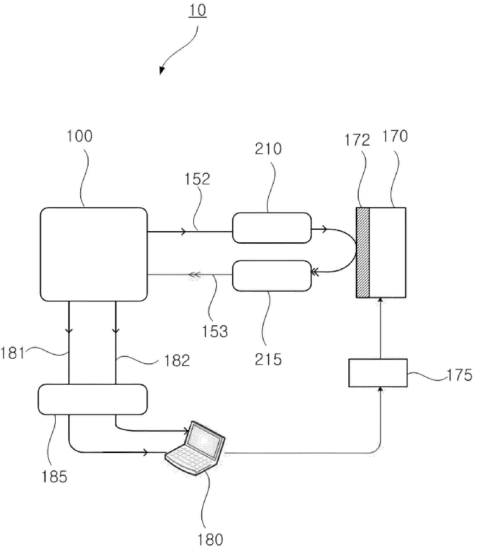
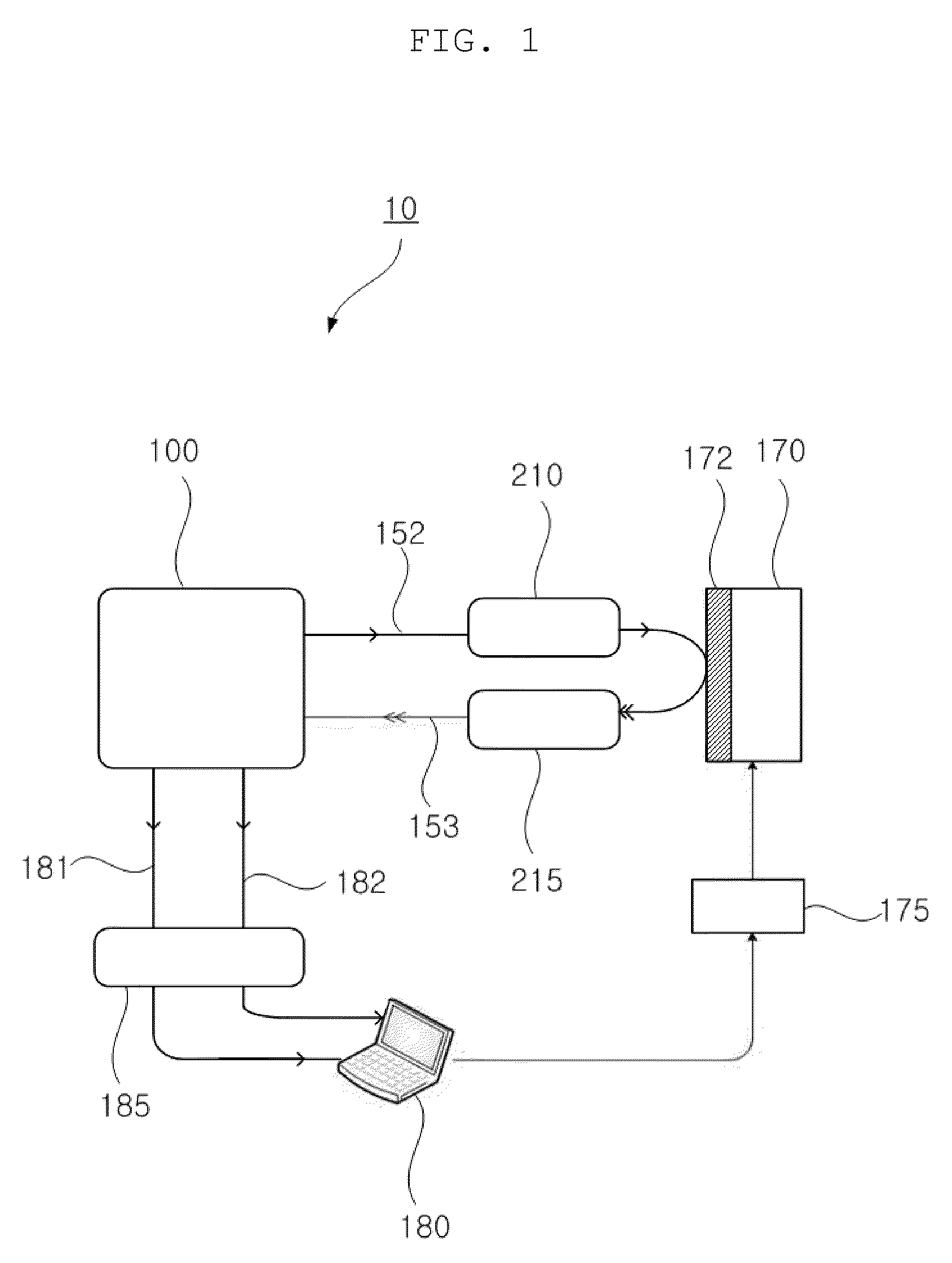
[0014]To achieve the above and other objects, the present invention provides a scanning microscope using a heterodyne interferometer, which includes: a heterodyne interferometer that provides a probe beam to a sample, focuses the probe beam onto the surface or inside of the sample under test, recollimates the probe beam reflected from or transmitted through the sample, sends the probe beam back to the interferometer, mixes the probe beam with the reference beam and, thereby, down converts the phase and amplitude modulation into a intermediate ...


PUM


Abstract

The present invention relates to a scanning microscope using a heterodyne interferometer, which can be used for mapping or imaging complex optical parameters such as physical structures and material properties of a sample under test. The heterodyne interferometer is designed to provide in- and quadrature-phase interference signal which can be used for extracting the phase and amplitude change induced on the probe beam. The phase and the amplitude of the probe beam, which is reflected from or transmitted through the sample, are modified by the physical structures and material properties of the sample. Therefore, by scanning the probe beam, local variations of the phase and amplitude can be mapped, and, thereby, three-dimensional microscopic physical structures and material properties can be imaged by processing the phase and amplitude values.

Description

FIELD OF THE INVENTION[0001]The present invention relates to a scanning microscope using a heterodyne interferometer, which can be used for mapping or imaging complex optical parameters such as physical structures and material properties of a sample under test.DESCRIPTION OF THE RELATED ART[0002]An interferometric measuring system is a system that combines a probe beam and a reference beam by using a beam splitter (BS) and measures the intensities of two output beams from the corresponding output ports of the BS by using two separate photodetectors. From now on, the output electric signal from each photodetector will be referred to as an electrical signal. When the probe beam and the reference beam have the same frequency, the system is referred to as a homodyne interferometer and the system is referred as a heterodyne interferometer when the frequencies of the probe beam and the reference beam are different.[0003]In the case of a homodyne interferometer, the intensities of the outp...

Claims


Application Information

Patent Timeline
IPC IPC(8): G01B9/02
CPCG01B9/02003G01B9/02081G01B2290/70G01B9/0207H01J37/26H01J37/28
Inventor CHO, KYUMANKWON, KANG-HYUK
Owner IND UNIV COOP FOUND SOGANG UNIV
Why Eureka
Try Eureka