

Shaped cooling holes for reduced stress
- Summary
- Abstract
- Description
- Claims
- Application Information
AI Technical Summary
Benefits of technology
Problems solved by technology
Method used
Image


Examples
Embodiment Construction
[0017]The subject matter of the present invention is described with specificity herein to meet statutory requirements. However, the description itself is not intended to limit the scope of this patent. Rather, the inventors have contemplated that the claimed subject matter might also be embodied in other ways, to include different components, combinations of components, steps, or combinations of steps similar to the ones described in this document, in conjunction with other present or future technologies.
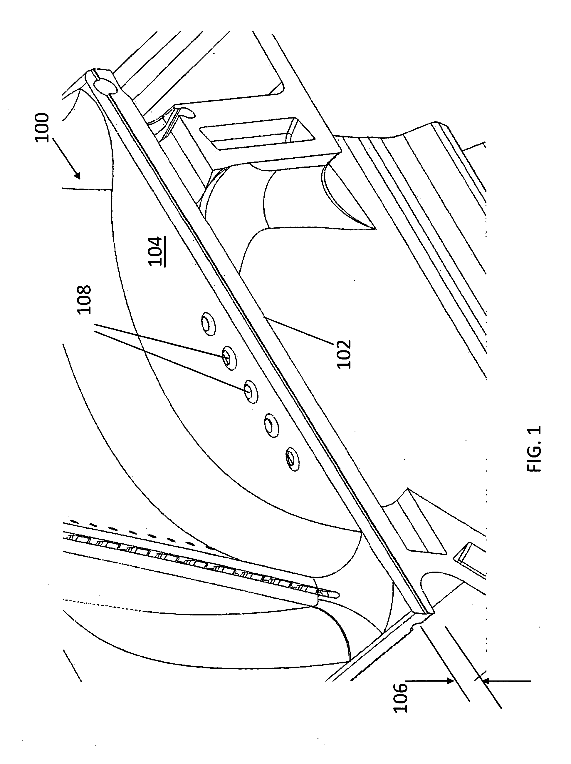
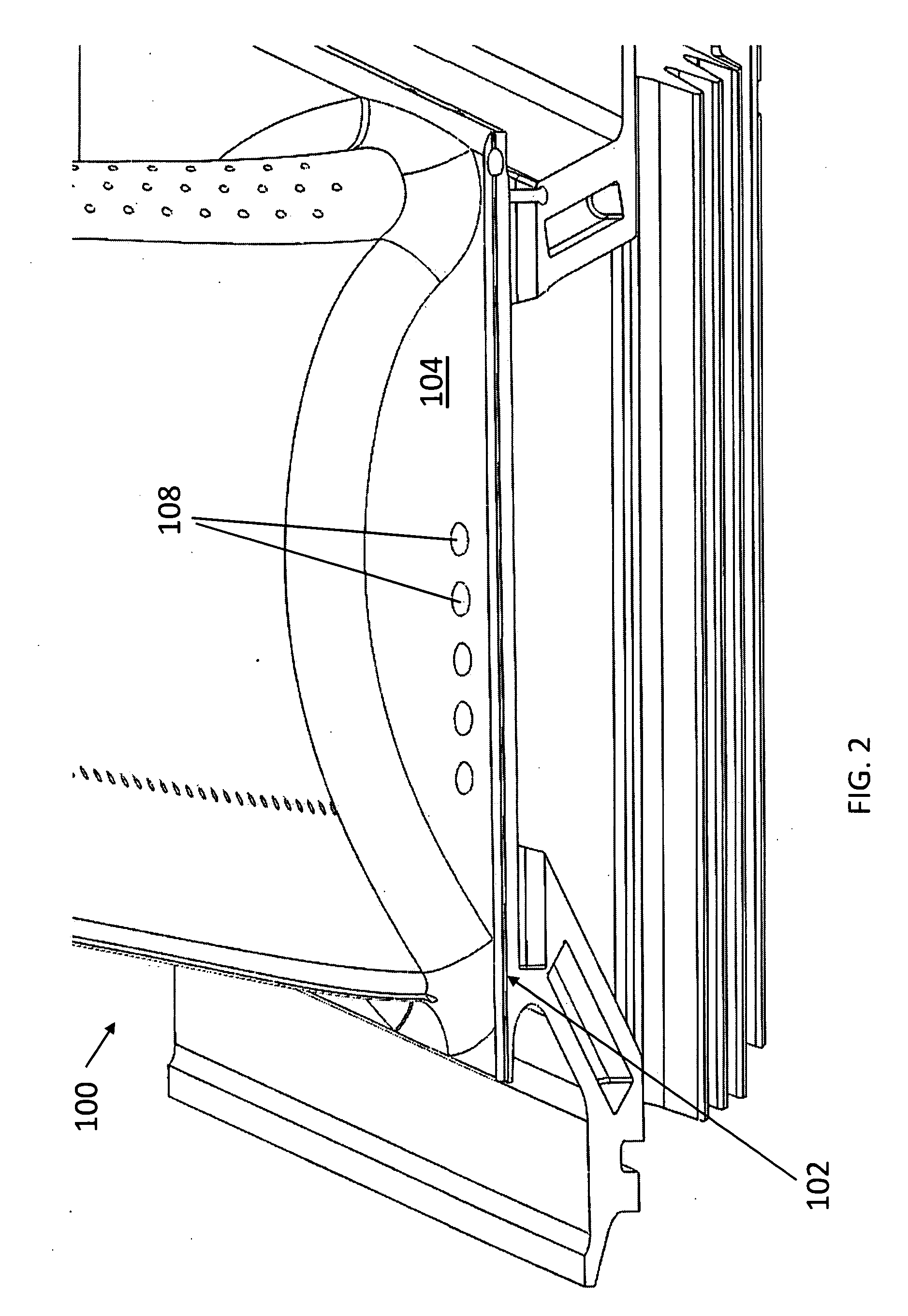
[0018]An embodiment of the present invention is shown in conjunction with a gas turbine component 100, such as a turbine vane blade, in FIGS. 1 and 2. The component 100 has a first surface 102 and a second surface 104 that is separated from the first surface by a thickness 106 of material. Located in the component 100 is a plurality of cooling holes 108. The plurality of cooling holes 108 have a generally elliptical shape that tapers in cross section from the first surface 102 to th...
PUM
 Abstract
Description
Claims
Application Information