Amplification system for interference suppression in wireless communications

a technology of interference suppression and wireless communication, applied in the direction of amplifiers, antennas, electricly long antennas, etc., can solve the problems of low power efficiency of mobile telecommunication equipment, low power output efficiency of stationary communication equipment, and the quality of rf signal radiated to an open space that needs to be extremely high, so as to achieve the effect of increasing signal strength

Inactive Publication Date: 2010-05-27
JANG SEI JOO
View PDF12 Cites 9 Cited by
  • Summary
  • Abstract
  • Description
  • Claims
  • Application Information

AI Technical Summary

Benefits of technology

[0010]An amplification system including a high gain amplifier, filter module and low gain amplifier. The high gain amplifier for receiving an input RF signal and processing the input RF signal to produce a first amplified signal while the high gain amplifier is operating near its saturation point. The filter module having at least one band pass filter to receive the first amplified signal and process the first amplified si

Problems solved by technology

However, the power output efficiency of equipment in stationary communication units is notoriously “low”, at only a little better than ten percent.
One of the reasons for such low power efficiency of mobile telecommunication equipment is that the quality of RF signal radiated to an open space needs to be extremely high.
Most PA exhibit some degree of nonlinearity near their saturation point, which causes an increase in the spectral growth of the output power density and leads to distortion of the ACLR of the output signal.
Therefore, current PAs employed in typical amplification systems a

Method used


Image

  • Amplification system for interference suppression in wireless communications
  • Amplification system for interference suppression in wireless communications
  • Amplification system for interference suppression in wireless communications

Examples


Embodiment Construction

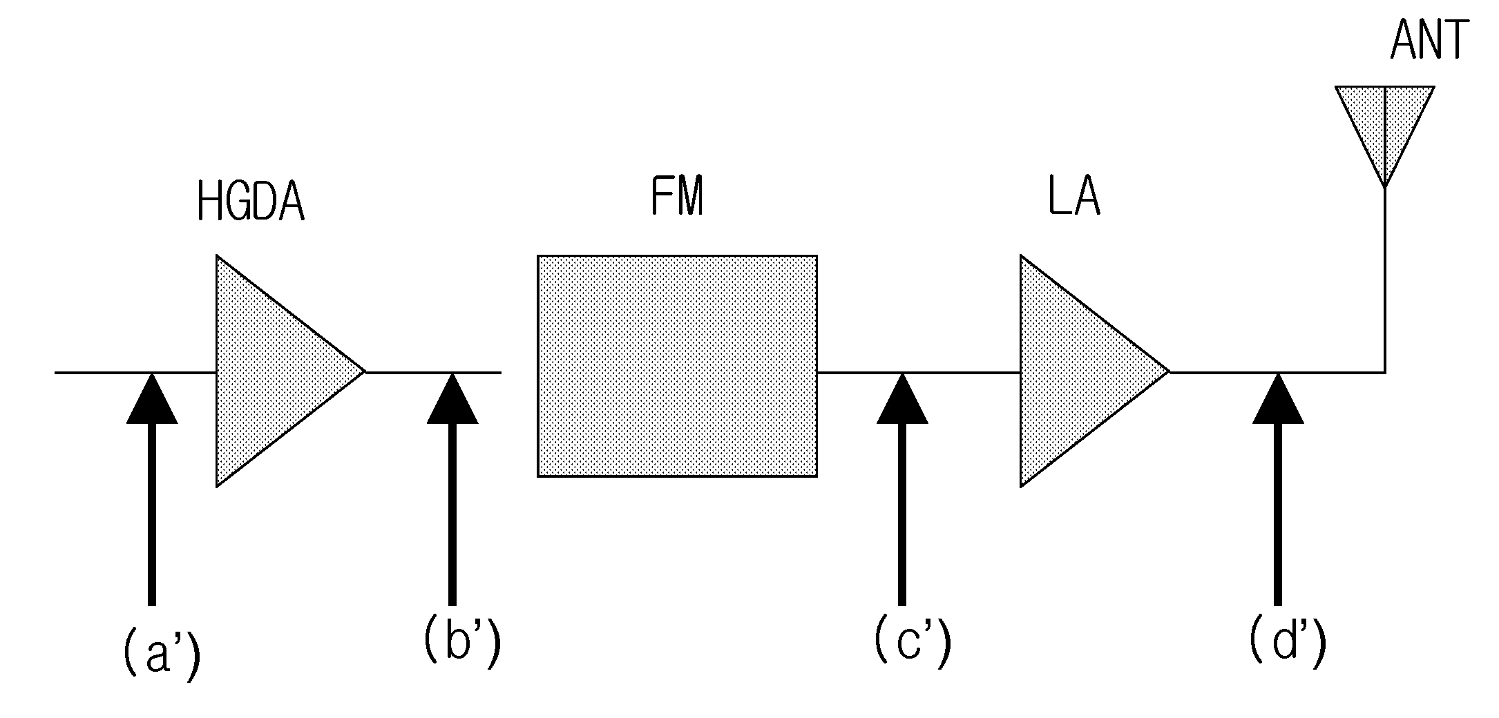
[0032]The present invention is an amplification system to suppress interference in mobile telecommunication equipment, while increasing RF power output efficiency. The present invention is also a method of implementing the suppression of interference in mobile telecommunication equipment, while increasing RF power output efficiency of the in mobile telecommunication equipment and maintaining the required ACLR. Whereby, RF power output efficiency is defined as: total RF radiation power of the stationary communication unit divided by DC electric power required by an output power amplifier of the stationary communication unit in order to generate that total RF radiation power. The amplification system of the present invention provides signal characteristics of a large isolation, sharp skirt, a good ripple, and acceptable S11 and S12 properties.

[0033]The amplification system of the present invention includes a High Gain Driving Amplifier (HGDA), Filter Module (FM), and a Linearization R...


PUM


Abstract

An amplification system including a high gain amplifier, filter module and low gain amplifier. The high gain amplifier for receiving an input RF signal and processing the input RF signal to produce a first amplified signal while the high gain amplifier is operating near its saturation point. The filter module having at least one band pass filter to receive the first amplified signal and process the first amplified signal to remove unwanted characteristics of the first amplified signal to produce a processed first amplified signal. The low gain amplifier receiving the processed first amplified signal and processing the processed first amplified signal to produce a second amplified signal that has an increase in signal strength over the processed first amplified signal while the low gain amplifier is operating near its saturation point.

Description

[0001]This application claims the benefit under Title 35, United States Code, Section 119 and incorporates by reference Korean applications 10-2008-0116908, filed Nov. 24, 2008; 10-2008-0116929, filed Nov. 24, 2008; 10-2008-0116958, filed Nov. 24, 2008; 10-2008-0116971, filed Nov. 24, 2008; 10-2008-0118909, filed Nov. 27, 2008; and 10-2008-0118915, filed Nov. 27, 2008.BACKGROUND[0002]The present invention generally relates to amplification of wireless signals in communication equipment. More specifically, the present invention relates to amplification of wireless signals efficiently.[0003]Mobile telecommunication networks employ stationary communication units such as base stations and repeaters to allow communications between wireless devices, such as cell phones and other devices. The repeaters are used between the base station and the wireless devices to enhance the quality of the RF signal, extend service area around the base stations and reduce the cost of the network. The outpu...

Claims


Application Information

Patent Timeline
IPC IPC(8): H04B1/04
CPCH03F1/0288H04B1/0475H03F1/3241H03F1/3223
Inventor JANG, SEI-JOO
Owner JANG SEI JOO
Why Eureka
Try Eureka