Liquid dispensing systems encompassing gas removal

Active Publication Date: 2010-06-03
ADVANCED TECH MATERIALS INC
View PDF63 Cites 74 Cited by
  • Summary
  • Abstract
  • Description
  • Claims
  • Application Information

AI Technical Summary

Benefits of technology

[0020]The present invention relates to dispensing systems, useful for supply of fluid materials to a tool, process or location at or in which the fluid is utilized, and t

Problems solved by technology

In the field of microelectronic device manufacturing, the need for suitable packaging is particularly compelling for a wide variety of liquids and liquid-containing compositions, since any contaminants in the packaged material, and/or any ingress of environmental contaminants to the contained material in the package, can adversely affect the microelectronic device products that are manufactured with such liquids or liquid-containing compositions, rendering the microelectronic device products deficient or even useless for their intended use.
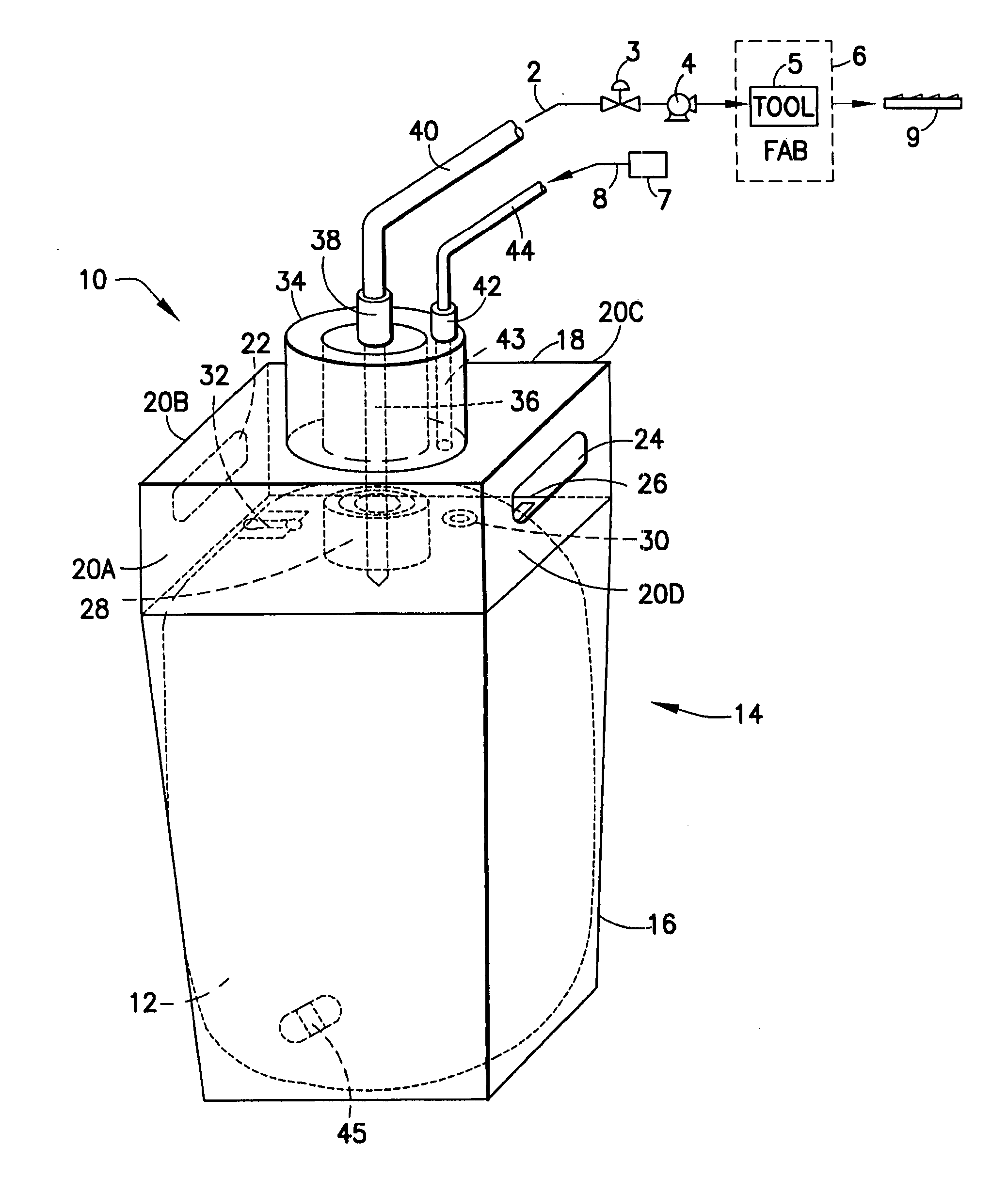
Headspace (extra air at the top of a liner) and microbubbles present a significant process problem for liquid dispensing from liner-based packages, e.g., in panel display (FPD) and integrated circuit (IC) manufacturing facilities.
As a result, gas from the headspace may become entrained in the dispensed liquid and produce a heterogeneous, a multi-phase dispensed fluid stream that is deleterious to the process or product for which the dispensed liquid is being utilized.
Further, the presence of gas from the headspace in the dispensed liquid can result in a malfunctioning or error in operation of fluid flow sensors, flow controllers, and the like.
A related problem, incident to the use of packages containing liquid compositions, is permeation or in-leakage of gas into the contained liquid and solubilization and bubble formation in the liquid.
When the liquid subsequently is dispensed, pressure drop in the dispensing lines and downstream instrumentation and equipment may cause liberation of formerly dissolved gas, resulting in the formation of bubbles in the stream

Method used


Image

  • Liquid dispensing systems encompassing gas removal
  • Liquid dispensing systems encompassing gas removal
  • Liquid dispensing systems encompassing gas removal

Examples


Example

[0051]The present invention relates to dispensing systems for the supply of fluid materials, and to methods of fabrication and use of such systems. In a specific aspect, the invention relates to a liner-based liquid containment systems for storage and dispensing of chemical reagents and compositions, e.g., high purity liquid reagents and chemical mechanical polishing compositions used in the manufacture of microelectronic device products.

[0052]In the use of liner-based packages for storage and dispensing of fluid materials, wherein the liner is mounted in a rigid or semi-rigid outer vessel, the dispensing operation may involve the flow of a pressure-dispense gas into the vessel, exteriorly of the liner, so that the pressure exerted by the gas forces the liner to progressively be compacted so that the fluid material in the liner in turn is forced to flow out of the liner. The thus-dispensed fluid material may be flowed to piping, manifolding, through connectors, valves, etc. to a loc...


PUM


Abstract

Systems are described for delivery of a wide variety of materials in which liquid and gas or vapor states are concurrently present, from a package preferably including a fluid-containing collapsible liner. Headspace gas is removed from a pressure dispensing package prior to liquid dispensation therefrom, and ingress gas is removed thereafter during dispensation operation. At least one sensor senses presence of gas or a gas-liquid interface in a reservoir or gas-liquid separation region. A gas removal system including an integral reservoir, at least one sensor, and at least one flow control elements may be included within a connector adapted to mate with a pressure dispensing package, for highly efficient removal of gas from the liquid being dispensed from the container.

Description

STATEMENT OF RELATED APPLICATIONS[0001]This application claims benefit of the following three patent applications: U.S. patent application Ser. No. 60 / 813,083 filed on Jun. 13, 2006; U.S. patent application Ser. No. 60 / 829,623 filed on Oct. 16, 2006; and U.S. patent application Ser. No. 60 / 887,194 filed on Jan. 30, 2007.FIELD OF THE INVENTION[0002]The present invention relates to dispensing systems, such as are utilized to effect supply of fluid materials for use thereof. In a specific aspect, the invention relates to pressure-dispensing systems, wherein liquid or other fluid material is discharged from a source vessel by displacement with a pressurized medium, e.g., air or liquid, and to associated aspects relating to fabrication, operational processes, and deployment of such systems.DESCRIPTION OF THE RELATED ART[0003]In many industrial applications, chemical reagents and compositions are required to be supplied in a high purity state, and specialized packaging has been developed ...

Claims


Application Information

Patent Timeline
IPC IPC(8): B67D7/00B67D7/06B65D35/56B67D7/08B65D83/00
CPCB67D7/0261B65D83/62B67D7/763Y10T137/313B65D83/00B67D1/08B67D7/72G01F11/00
Inventor WARE, DONALD D.TOM, GLENN M.DATHE, PAULKOLAND, AMYGEROLD, JASONMIKKELSEN, KIRKO'DOUGHERTY, KEVIN T.CISEWSKI, MICHAEL A.
Owner ADVANCED TECH MATERIALS INC
Why Eureka
Try Eureka