MIMO communication system having deterministic communication path and antenna arrangement method therfor

a communication system and deterministic technology, applied in the field of split-vision multiplexing methods, can solve the problems of fading phenomenon, mimo itself is no longer a new technology, application of mimo to a fixed point communication has not been fully examined, etc., and achieve the effect of saving space and maximising capacity

Active Publication Date: 2010-06-03
NEC CORP
View PDF10 Cites 45 Cited by
  • Summary
  • Abstract
  • Description
  • Claims
  • Application Information

AI Technical Summary

Benefits of technology

[0021]As described above, according to the first MIMO communication system having deterministic channels and an antenna arrangement method therefor, even if a reflected wave other than the direct wave is present during line-of-sight communication, it is possible to ensure orthogonality.
[0022]According to the second MIMO communication system having deterministic channels and an antenna arrangement method therefor, even if a reflected wave other than the direct wave is present during line-of-sight communication, it is possible to ensure orthogonality in an antenna configuration where space saving is achieved due to vertical arrangement of the antennas.
[0023]According to the third MIMO communication system having deterministic channels and an antenna arrangement method therefor, even if a reflected wave other than the direct wave is present during line-of-sight communication, it is possible to ensure orthogonality with the maximum capacity.
[0024]According to the fourth MIMO communication system having deterministic channels and an antenna arrangement method therefor, even if a reflected wave other than the direct wave is present during line-of-sight communication, it is possible to ensure orthogonality with the maximum capacity in an antenna configuration where space saving is achieved due to vertical arrangement of the antennas.

Problems solved by technology

A technique using a MIMO has become popular in the field of wireless communication, and the MIMO itself is becoming no longer a new technology.
However, conventional techniques using the MIMO mainly focus on a mobile communication, and application of the MIMO to a fixed point communication has not been fully examined.
In a mobile communication radio channels, radio wave coming from a transmission antenna is reflected or scattered according to the surrounding terrain and reaches a receiver in the form of a group of waves, resulting in occurrence of fading phenomenon which has been an obstacle to achievement of high quality communication.
Under such a condition, it is difficult to ensure the deterministic channel matrix.
However, the above feedback information may increase system overhead.
This state, which is particularly analytically troublesome, may cause significant transition of the singular vectors.
As a major problem in the deterministic line-of-sight MIMO, there is a problem that carrier synchronization between antennas must be achieved on the transmission side or reception side in the above conventional method.
That is, the problem of the necessity of achievement of carrier synchronization between antennas imposes severe restriction on construction of the fixed point microwave communication system.

Method used


Image

  • MIMO communication system having deterministic communication path   and antenna arrangement method therfor
  • MIMO communication system having deterministic communication path   and antenna arrangement method therfor
  • MIMO communication system having deterministic communication path   and antenna arrangement method therfor

Examples


first example

[0203]As a first example of the present invention, a configuration example in which the matrix calculation is performed only on the transmission side will be described.

[Singular Value Diagonal Matrix Λ1 / 2]

[0204]In this example, the virtual orthogonal channels have the same value, so that singular value diagonal matrix Λ1 / 2 is represented by the following formula.

Λ1 / 2=[λ100λ2]=[2+2cosα002-2cosα]=[2002][Numeral67]

[Channel Matrix H]

[0205]In this example, the channel matrix H is represented by the following formula.

H=U·Λ1 / 2·VH=[1001]·[2002]·[12-j·jΦ2-j·2jΦ2]∴V=[V11V12V21V22]=[12j2j·-jΦ2-jΦ2]UH=[U11U12U21U22]=[1001]where;α=2π(dR22R) / γ=πγ·dR2R=π2[Numeral68]

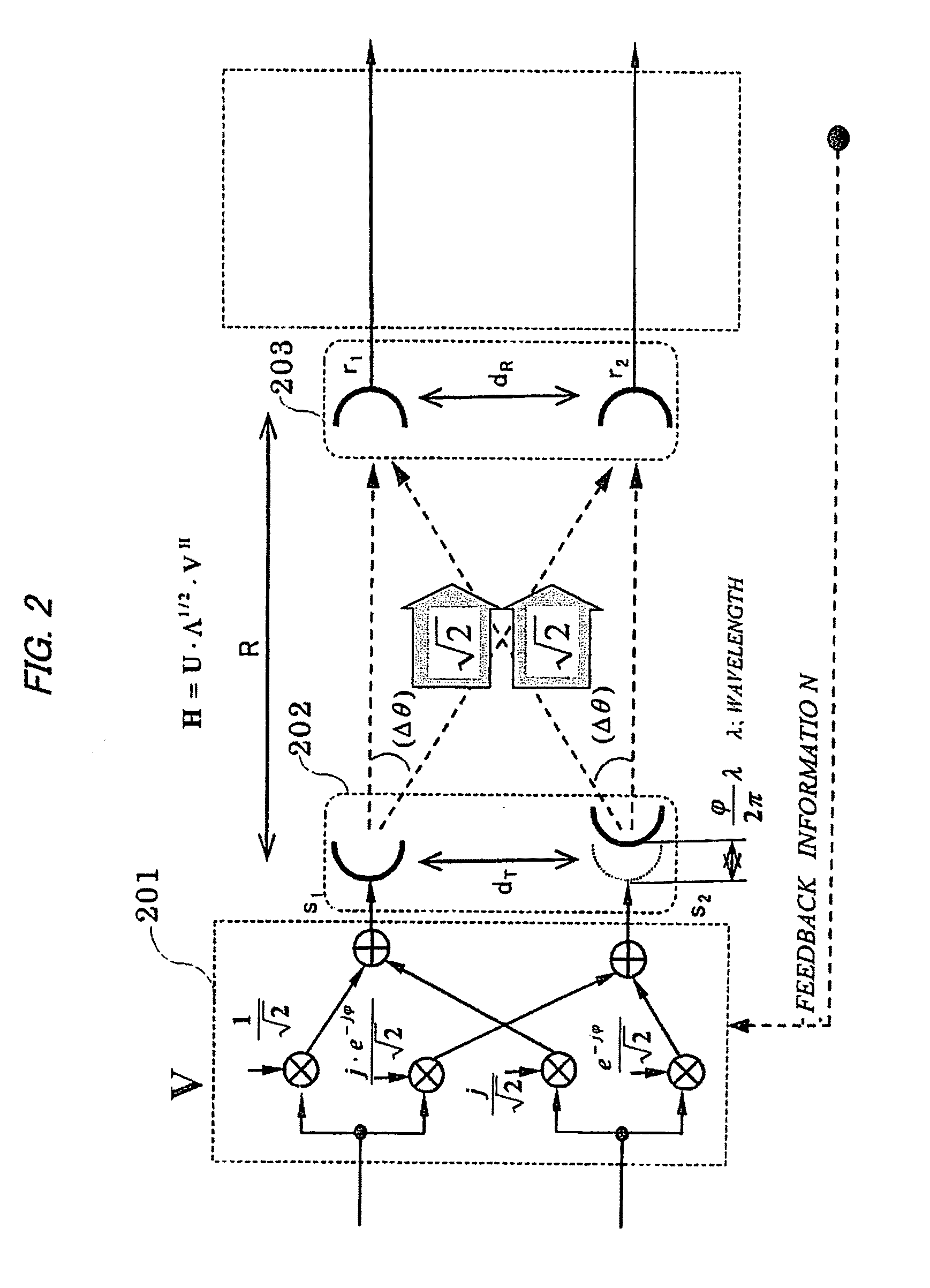
[0206]A configuration obtained based on the above result is shown in FIG. 2.

[0207]In FIG. 2, transmission signals processed by a transmission side matrix calculation processing section 201 based on the unitary matrix V are transmitted from a fixed antenna section 202 including a plurality of antennas as s1 and s2. The notation of the s1...

second example

[0210]As a second example of the present invention, a configuration example in which the matrix calculation is performed only on the transmission side in the virtual orthogonal channels having paths with different widths will be described.

[Singular Value Diagonal Matrix Λ1 / 2]

[0211]In this example, the virtual orthogonal channels have different values, so that singular value diagonal matrix Λ1 / 2 is represented by the following formula.

Λ1 / 2=[λ100λ2]=[2+2cosα002-2cosα]=[2cos(α2)002sin(α2)]=[(jα2+-jα2)00-j(ejα2--jα2)][Numeral69]

[Channel Matrix H]

[0212]In the present example, the channel matrix H is represented by the following formula.

H=U·Λ1 / 2·VH=[1-jα·jΦ-jα1·jΦ]=[1001]·[(jα2+-jα2)00-j(jα2--jα2)]·VH[Numeral70]

[0213]Accordingly, the following formula is satisfied.

VH=[(jα2+-jα2)00-j(jα2--jα2)]-1·[1-jα·jΦ-jα1·jΦ][Numeral71]

[0214]Here, the following formula is satisfied.

1(jα2+-jα2)=12·cos(α2),1-j(jα2--jα2)=12·sin(α2)[Numeral72]

[0215]Accordingly, the following formula is obtained.

VH=[12·cos(...

third example

[0229]As a third example of the present invention, a configuration example in which the unitary matrix calculation is performed only on the reception side and local oscillators are provided independently for respective antennas on the transmission side will be described.

[0230]This third configuration has the following features: the feedback information to be sent from the reception end to transmission end is not required; local oscillators may be provided independently for respective antennas on the transmission end; and exactly the same characteristics as those of the SVD method can be shown.

[Singular Value Diagonal Matrix Λ1 / 2]

[0231]In this example, the virtual orthogonal channels have the same value, so that singular value diagonal matrix Λ1 / 2 is represented by the following formula.

Λ1 / 2=[λ100λ2]=[2+2cosα002-2cosα]=[2002][Numeral79]

[Channel Matrix H]

[0232]In this example, the channel matrix H is represented by the following formula.

H=U·Λ1 / 2·VH=U·[2002]·[1001]where;Φ=ΦL+ΦA∴U=[U11U...


PUM


Abstract

A MIMO communication system having deterministic channels the orthogonality of which can be ensured even if a reflected wave other than the direct wave is present during line-of-sight communication is provided. The MIMO communication system is used in a line-of-sight environment and has deterministic channels between the transmission side where a plurality of transmission antennas are arranged and the reception side where a plurality of reception antennas are arranged. The transmission side, the reception side, or both transmission and reception sides of the MIMO communication system have a channel matrix calculation processing means for calculating a channel matrix for establishing an orthogonal channel as a communication channel. The transmission and reception antennas forming the channel matrix are horizontally arranged with respect to the ground.

Description

TECHNICAL FIELD[0001]The present invention relates to a space-division multiplexing method (hereinafter, referred to as “MIMO (Multiple-Input / Multiple-Output)” in a Line-Of-Sight (LOS) environment and, more particularly to a MIMO communication system having deterministic channels like a fixed point microwave communication system, and an antenna arrangement method therefore.BACKGROUND ART[0002]A technique using a MIMO has become popular in the field of wireless communication, and the MIMO itself is becoming no longer a new technology. However, conventional techniques using the MIMO mainly focus on a mobile communication, and application of the MIMO to a fixed point communication has not been fully examined. In a mobile communication radio channels, radio wave coming from a transmission antenna is reflected or scattered according to the surrounding terrain and reaches a receiver in the form of a group of waves, resulting in occurrence of fading phenomenon which has been an obstacle to...

Claims


Application Information

Patent Timeline
Patent Type & Authority Applications(United States)
IPC IPC(8): H04W40/00H04L27/28
CPCH04B7/04H04B7/0456H04B7/0854H04B7/0617H04L25/0204H04L25/0248H04L25/0242
Inventor MARU, TSUGUO
Owner NEC CORP
Why Eureka
Try Eureka