
Magnetic particle parallel processing apparatus permitting repeated use of container and method of magnetic particle parallel processing permitting repeated use of container

a technology of magnetic particle and parallel processing, which is applied in the direction of separation process, laboratory glassware, instruments, etc., can solve the problems of large working space, reduced working efficiency in space, and long working time, so as to save working area, prevent cross contamination due to liquid splashing, and process quickly

Inactive Publication Date: 2010-06-03
UNIVERSAL BIO RESEARCH CO LTD
View PDF7 Cites 25 Cited by
  • Summary
  • Abstract
  • Description
  • Claims
  • Application Information

AI Technical Summary

Benefits of technology

[0050]According to the first aspect or the tenth aspect, processing for newly feeding a liquid to the reaction container for use in the processing of magnetic particles by each step according to the processing content, and removing the whole amount of the liquid, is repeated. Moreover, while the residual liquid is being disposed into the liquid disposal tank with the magnetic particles attracted to the inner wall of the distal end of the processing nozzle, the liquid for use in the next step is fed to the reaction container to shift to the next processing step. Accordingly, the same container can be repeatedly used irrespective of the number of steps. Thus, there is no need of increasing the number of containers for used in processing, irrespective of the incremental number of steps, and the working area can be saved. In addition, the liquid for use in the next step is fed to the reaction container during a given timing for when the residual liquid is disposed from the processing nozzle on completion of each step. As a result, the time for previously dispensing the liquid for use in each processing step can be saved so that magnetic particles can be quickly processed.
[0051]The suspended state of the magnetic particles required for processing in the liquid can be achieved by the sucking and discharging operation with use of the processing nozzle. Therefore, the magnetic particles can be reliably sucked in the suspended state, and removed from the reaction container. In addition, since the agitation operation for suspending the magnetic particles is not necessary during processing, cross-contamination due to liquid splashing can be reliably prevented.
[0052]According to the second aspect or the twelfth aspect, the distal end of the flow channel of the reagent etc. feeder is relatively movably provided with respect to the reaction container, and the liquid required for processing is fed by inserting its distal end into the reaction container. Accordingly, the liquid can be fed by inserting the distal end into the reaction container only when feeding is needed. Therefore, the distal end of the reagent etc. feeder and the distal end of the processing nozzle will not conflict with each other in the reaction container. Hence the feeding and the processing can be smoothly performed, and cross-contamination due to these distal ends touching each other can be avoided. In particular, when the reagent etc. storage unit and the dispenser device are used as the reagent etc. feeder, the assembling operation can be readily done using common parts for the apparatus used in the processing nozzle. Therefore the production cost can be saved.
[0053]According to the third aspect, the distal ends of the flow channel and the processing nozzle are made movable, and the reaction container is provided to exist on both of the transfer pathway of the distal end of the flow channel and the transfer pathway of the distal end of the processing nozzle. By so doing, the reaction container can be formed in a fixed state, or on a shortest pathway through which the container can pass any point of the transfer pathways.
[0054]According to the fourth aspect, the reaction container and the liquid disposal tank are movably provided with respect to the distal end of the processing nozzle, whereby the momentum can be reduced as compared to the case where the distal end of the processing nozzle is moved, and the apparatus structure and the movement control can be simplified by unitedly moving the reaction container and the liquid disposal tank.
[0055]According to the fifth aspect, the reaction container and the liquid disposal tank are provided in the processing carriage and subjected to reciprocating movement along a straight line with respect to the distal end of the processing nozzle, whereby the apparatus structure and the movement control can be further simplified.

Problems solved by technology

For this reason, there has been a problem in that a large working space may be required, and the working efficiency in terms of space may be lowered.
Therefore, there has been a problem in that a lengthy working time may be required, and the working efficiency in terms of time may be impaired.

Method used


Image

  • Magnetic particle parallel processing apparatus permitting repeated use of container and method of magnetic particle parallel processing permitting repeated use of container
  • Magnetic particle parallel processing apparatus permitting repeated use of container and method of magnetic particle parallel processing permitting repeated use of container
  • Magnetic particle parallel processing apparatus permitting repeated use of container and method of magnetic particle parallel processing permitting repeated use of container

Examples


first embodiment

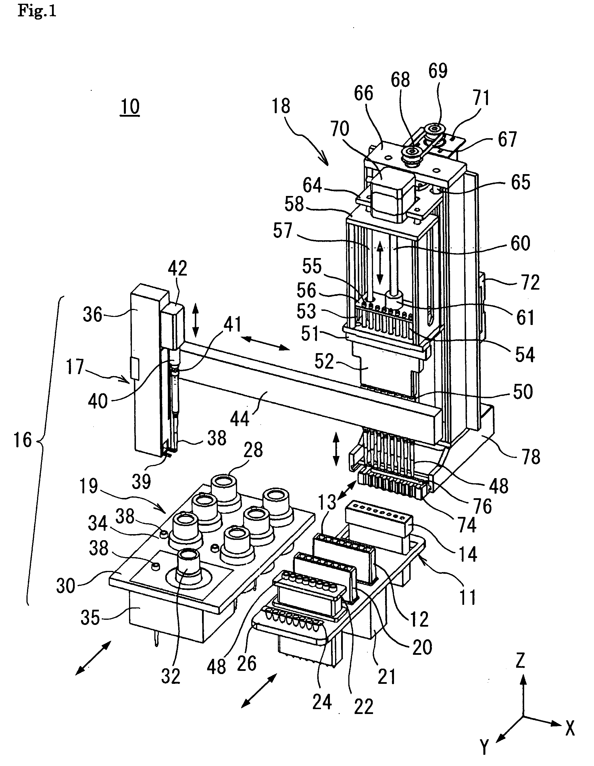
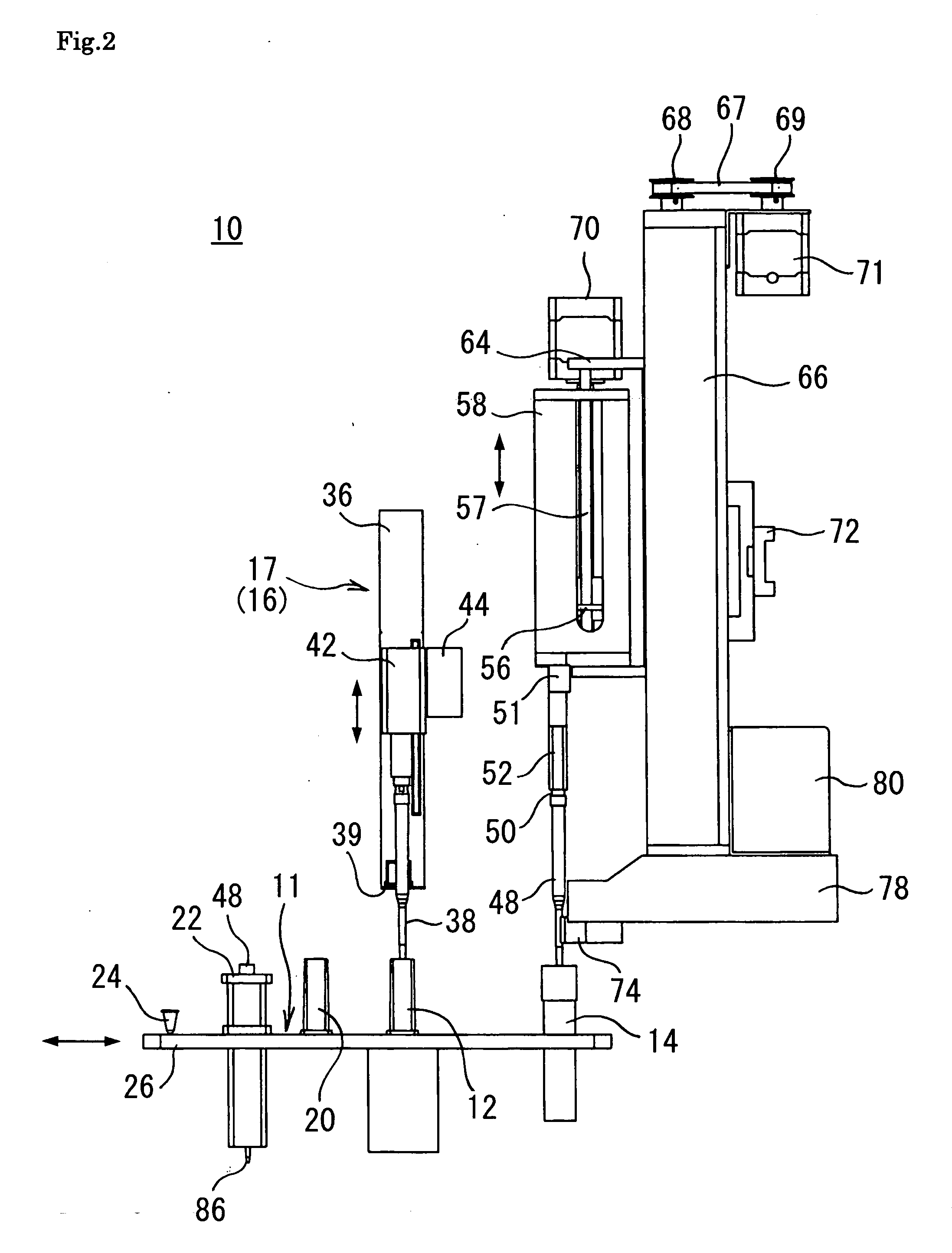
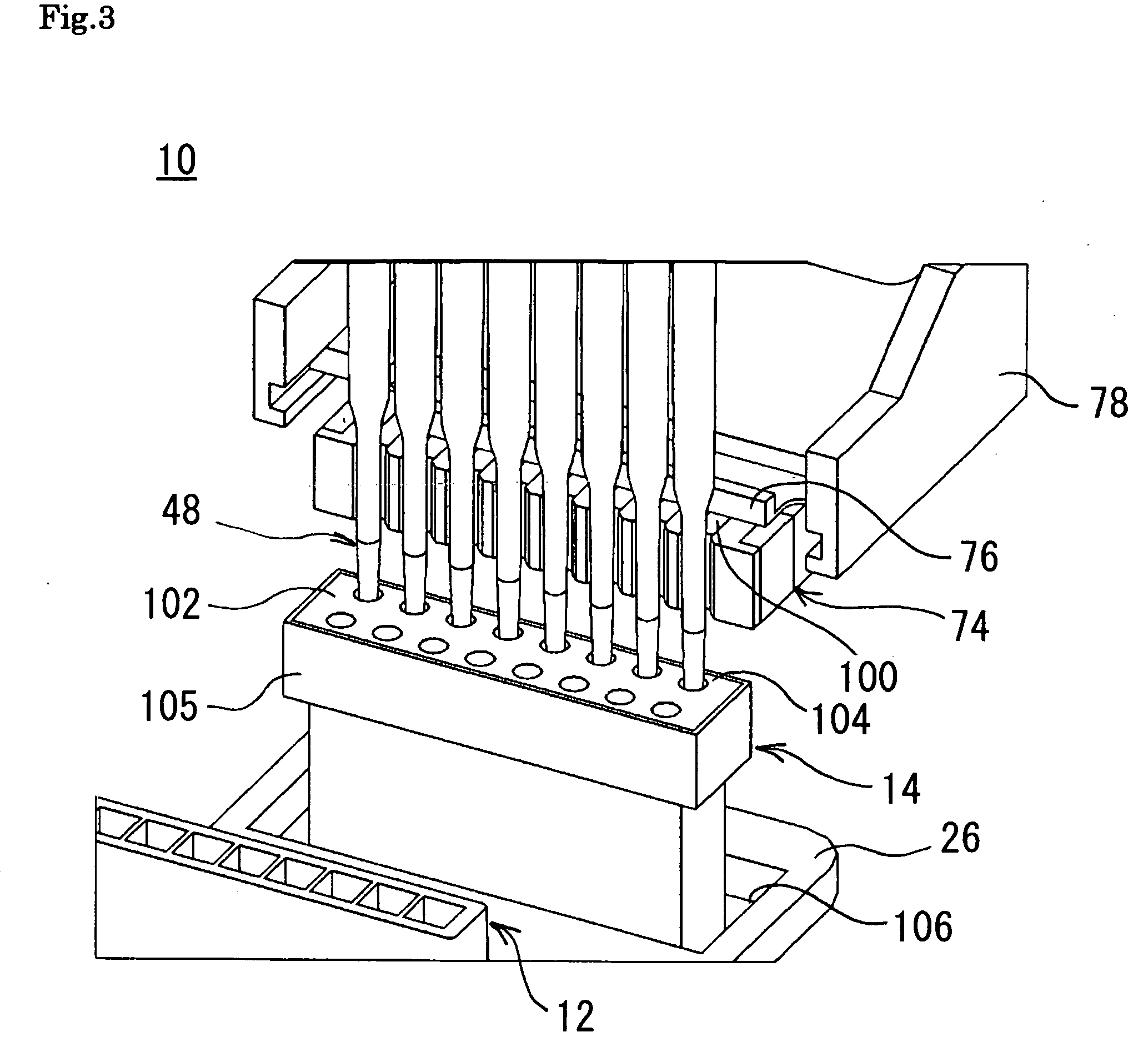
[0062]Next is a description of a magnetic particle parallel processing apparatus 10 permitting repeated use of a container according to the present invention, with reference to FIG. 1 through FIG. 7.

[0063]As shown in FIG. 1, the magnetic particle parallel processing apparatus 10 permitting repeated use of a container comprises: a processing carriage 11 having at least a reaction container 12 for storing a liquid to be used, and a liquid disposal tank 14 capable of storing a liquid to be disposed; a reagent etc. feeder 16 with at least one flow channel for feeding at least two types of liquids selected from the group consisting of two or more types of solutions and a magnetic particle suspension according to the processing content, at a given amount and at a given timing, to the reaction container 12; and a magnetic separator 18 for sucking the liquid from the reaction container 12 and discharging the liquid into the disposal tank 14, as well as applying a magnetic field to the sucke...

second embodiment

[0096]FIG. 8 shows the magnetic particle parallel processing apparatus 110 permitting repeated use of a container according to a The magnetic particle parallel processing apparatus 110 permitting repeated use of a container comprises: a processing carriage 111 having a reaction container 112 capable of storing a liquid to be used with wells arrayed in a matrix form of 8 rows×12 columns, and a liquid disposal tank 114 capable of storing a liquid to be disposed; a reagent etc. feeder 116 with at least one (twelve in this example) flow channel for feeding at least two types of liquids selected from the group consisting of two or more types of solutions and a magnetic particle suspension according to the processing content, at a given amount and at a given timing, to the reaction container 112; and a magnetic separator 118 for sucking the liquid from the reaction container 112 and discharging the liquid into the disposal tank 114, as well as applying a magnetic field to the sucked liqu...

third embodiment

[0107]FIG. 10 shows the magnetic particle parallel processing apparatus 170 permitting repeated use of a container in which the same reference symbols are used for components the same as those in FIG. 8, and description thereof is omitted. The magnetic particle parallel processing apparatus 170 permitting repeated use of a container comprises: a processing carriage 172 having a reaction container 112 capable of storing a liquid to be used with wells arrayed in a matrix form of 8 rows×12 columns; a liquid disposal tank 114 capable of storing a liquid to be disposed; a reagent etc. feeder 116 with at least one (twelve in this example) flow channel for feeding at least two types of liquids selected from the group consisting of two or more types of solutions and a magnetic particle suspension according to the processing content, at a given amount and at a given timing, to the reaction container 112; and a magnetic separator 118 for sucking the liquid from the reaction container 112 and...


PUM

PropertyMeasurementUnit
Lengthaaaaaaaaaa
Diameteraaaaaaaaaa
Magnetic fieldaaaaaaaaaa

Abstract

To provide a magnetic particle parallel processing apparatus permitting repeated use of a container, and a method of magnetic particle parallel processing permitting repeated use of a container, with which the rate of repeated use of a container is enhanced to thereby achieve a saving in the working space and a saving in the working time. The apparatus comprises: at least one reaction container; a liquid disposal tank; a reagent etc. feeder with at least one flow channel for feeding at least one type of liquid selected from the group consisting of two or more types of solutions and a magnetic particle suspension according to the processing content, at a given amount and at a given timing, to the reaction container; and a magnetic separator which has at least one processing nozzle with a distal end insertable into the reaction container and the liquid disposal tank, for sucking and discharging a liquid through the distal end, and which also has a magnetic means capable of applying a magnetic field to the interior of the distal end to thereby attract magnetic particles contained in the liquid inside the distal end to the inner wall thereof to effect separation of the magnetic particles, and canceling the magnetic field to thereby release the attracted magnetic particles and re-suspend the same in a liquid.

Description

TECHNICAL FIELD [0001]The present invention relates to a magnetic particle parallel processing apparatus permitting repeated use of a container, and a method of magnetic particle parallel processing permitting repeated use of a container.BACKGROUND ART [0002]Conventionally, in order to process a biological substance such as DNA, solutions such as; a magnetic particle suspension for use in the processing, a specimen solution, a reagent solution required for the processing of the specimen, a washing liquid, and the like are dispensed from a group of reagent etc. containers previously storing these solutions, and arrayed in accordance with the order of processing, in two or more liquid storage units for use in the processing, using a dispenser device. After the solutions have been arrayed, the magnetic particle suspension is sucked from and discharged into the first liquid storage unit using at least one processing nozzle which has at least one distal end insertable into the respective...

Claims


Application Information

Patent Timeline
IPC IPC(8): C40B50/18C40B60/14
CPCG01N35/0098Y10T436/25375G01N2035/1053G01N35/1065
Inventor TAJIMA, HIDEJI
Owner UNIVERSAL BIO RESEARCH CO LTD
Learn More