Vertical take off and landing unmanned aerial vehicle airframe structure

an unmanned aerial vehicle and vertical take-off technology, applied in the field can solve the problems of limited further penetration of unmanned aerial vehicles into civil applications, limited use of unmanned aerial vehicles in civil applications, and the overall weight of a completed unmanned aerial vehicle may fall below the limit, so as to reduce weight and cost, high structural integrity, and reduce weight and cost

Inactive Publication Date: 2010-06-10
HONEYWELL INT INC
View PDF50 Cites 55 Cited by
  • Summary
  • Abstract
  • Description
  • Claims
  • Application Information

AI Technical Summary

Benefits of technology

[0011]The present application is directed to a vertical take off and landing (VTOL) unmanned aerial vehicle (UAV) that is selectively constructed out of composites, metals, and foams in a manner so as to reduce weight and cost, allow for controlled disintegration by selective implementation of frangible elements, and provide an overall endurance at least approximately equivalent to larger liquid fueled UAV's, for example. A UAV design is provided that separates aerodynamic elements from structural elements, and chooses corresponding materials for each class of elements so as to reduce weight, maintain high structural integrity, and provides a frangible airframe structure. For example, aerody

Problems solved by technology

While UAV's have been utilized extensively in military roles, their use in civil applications has been limited due to cost concerns, export regulations (such as International Traffic in Arms Regulations—ITAR), civil airspace regulations, and safety regulations, for example.
Additionally, various regulations related to autonomous flying objects having a weight that could pose a hazard to life a

Method used


Image

  • Vertical take off and landing unmanned aerial vehicle airframe structure
  • Vertical take off and landing unmanned aerial vehicle airframe structure
  • Vertical take off and landing unmanned aerial vehicle airframe structure

Examples


Embodiment Construction

[0039]Aspects of the present application describe a system and method for construction of a light-weight unmanned aerial vehicle (UAV). Aerodynamic and structural elements are selected corresponding to required performance characteristics. Mechanical elements are designed to provide dual functionality and decrease a part count and cost of a corresponding UAV.

[0040]Although the following disclosure references a double ducted hovering air-vehicle, it should be appreciated that the present embodiments have a broader applicability in the field of air-borne vehicles. Particular configurations discussed in examples can be varied and are cited to illustrate example embodiments.

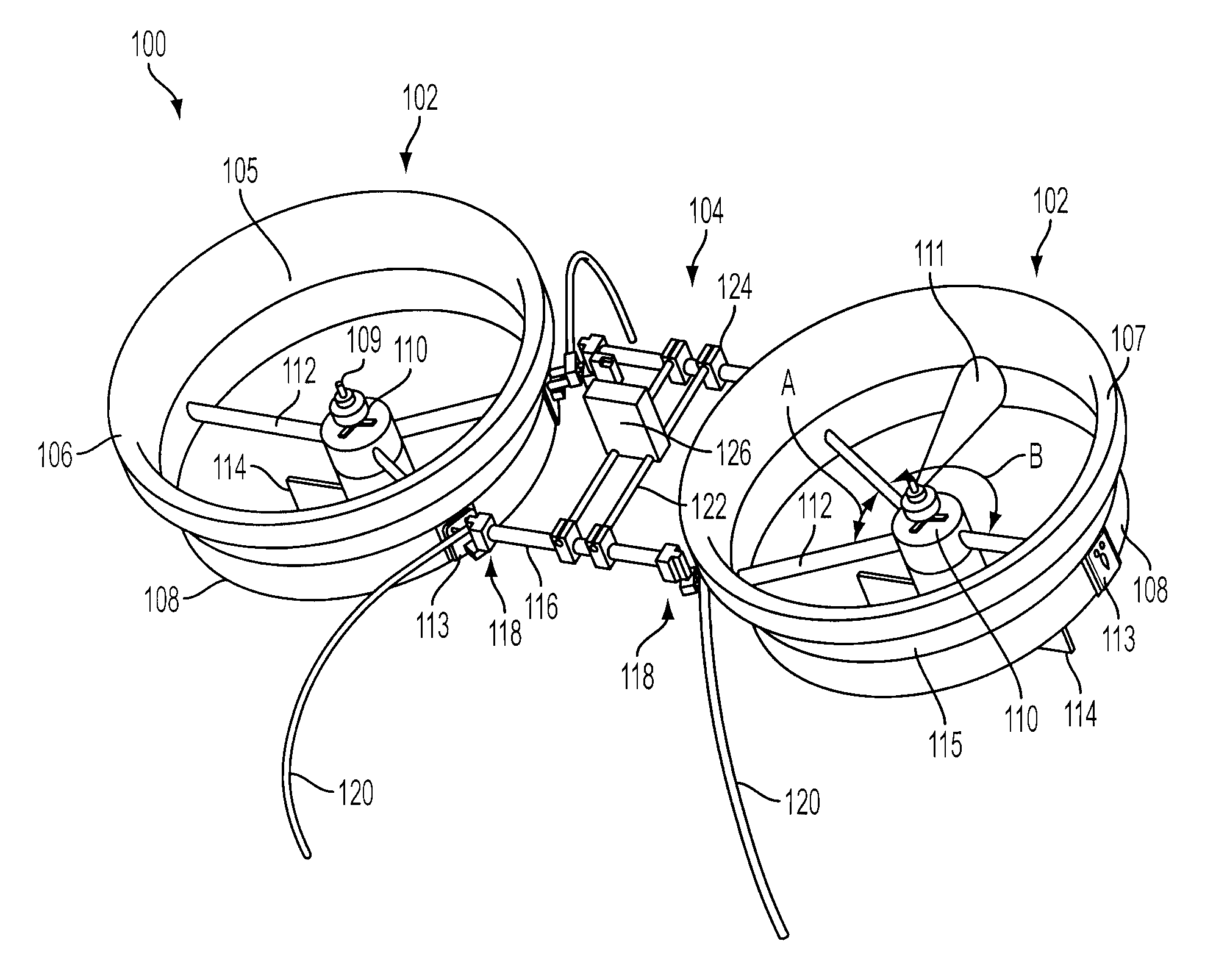
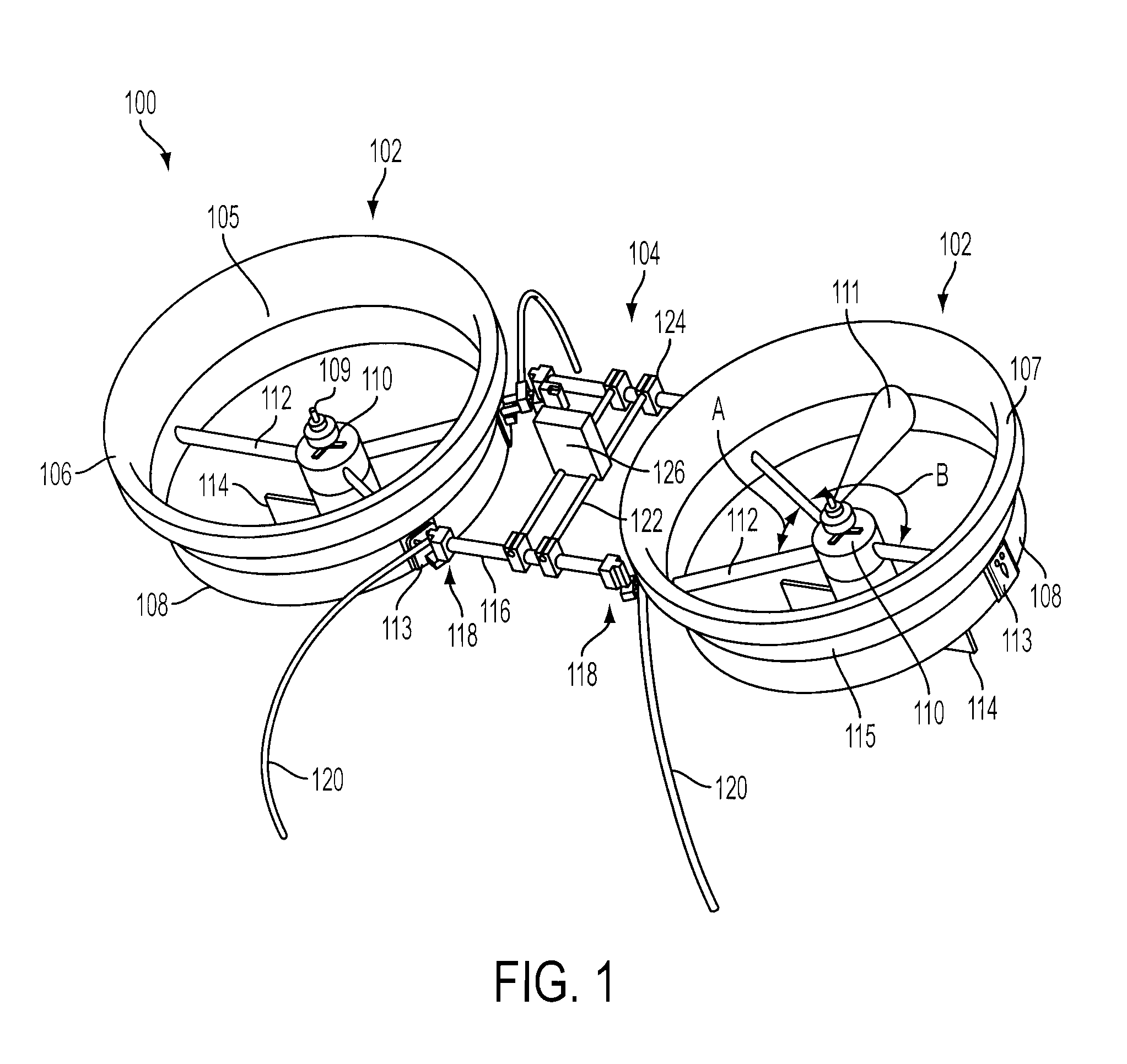
[0041]As set forth in FIG. 1, a UAV 100 according to one embodiment includes ducted fan assemblies 102 interconnected via duct linkage assembly 104. The UAV 100 includes legs 120 to keep the fan assemblies 102 and duct linkage assembly 104 from touching the ground. Although FIG. 1 sets forth two ducted fan assemblies...


PUM

PropertyMeasurementUnit
Weightaaaaaaaaaa
Forceaaaaaaaaaa
Angleaaaaaaaaaa

Abstract

An unmanned aerial vehicle selectively formed of high strength composite structural part portions and lightweight aerodynamic foam portions to provide a low-cost and lightweight UAV that comports with export, civil airspace, and safety regulations. To further to reduce an overall weight of the UAV, mechanical elements are designed to provide multiple functionalities. Structural elements may be manufactured in same or similar non-specialized processes, and non-structural elements manufactured in same or similar non-specialized processes, reducing overall manufacturing costs. Materials and bonding elements are selected to provide frangibility and yet maintain normal flight structural integrity.

Description

CROSS REFERENCE TO RELATED APPLICATIONS[0001]This application also claims priority to provisional U.S. Application No. 61 / 120,681, filed on Dec. 8, 2008, the entire contents of which are herein incorporated by reference.BACKGROUND[0002]1. Field Of The Invention[0003]The present invention relates, in general, to the field of unmanned aerial vehicle (UAVs). More specifically, it is directed to the field of UAVs capable of vertical take-offs and landings (VTOLs) with one or more ducted fans as the propulsion system.[0004]2. Description of the Related Art[0005]An unmanned aerial vehicle (UAV) is an unpiloted and / or remotely controlled aircraft. UAVs can be either remotely controlled or flown autonomously based on pre-programmed flight plans or more complex dynamic automation and vision systems. UAVs are currently used in a number of military roles, including reconnaissance and attack scenarios. An armed UAV is known as an unmanned combat air vehicle (UCAV).[0006]UAVs are also used in a ...

Claims


Application Information

Patent Timeline
IPC IPC(8): B64C29/04B64C1/00B21D39/03B23P15/02
CPCB64C27/20B64C39/024Y10T29/49826B64C2201/108Y10T29/49336B64C2201/027B33Y80/00B64U10/13B64U30/20
Inventor GOOSSEN, EMRAY
Owner HONEYWELL INT INC
Why Eureka
Try Eureka