Extreme ultraviolet light source apparatus

a light source and ultraviolet light technology, applied in the field of extreme ultraviolet (euv) light source devices, can solve the problems of difficult optics location adjustment, inability to supply euv light to an exposure unit to perform exposure, and inability to observe the image of the mtv emission point to perform automatic alignmen

Active Publication Date: 2010-06-10
GIGAPHOTON
View PDF10 Cites 85 Cited by
  • Summary
  • Abstract
  • Description
  • Claims
  • Application Information

AI Technical Summary

Benefits of technology

[0017]According to the one aspect of the present invention, by detecting the profile of the light split by the splitter optical element provided in the optical path of the light reflected by the EUV collector mirror, the location or posture shift of the EUV collector mirror can be detected.

Problems solved by technology

Here, the driver laser beam and the EUV light are invisible light, and therefore, the location adjustment of the optics has been not easy.
However, according to the above-mentioned alignment method, there have been the following problems because the IF location sensor is inserted into an optical path of EUV light and blocks the EUV light at observation of the image of the EUV emission point.
(1) While the image of the EUV emission point is observed, it is impossible to supply EUV light to an exposure unit to perform exposure.
(2) When the EUV collector mirror is replaced, it is impossible to observe the image of the MTV emission point to perform automatic alignment.
(3) When the optics is out of alignment due to changes in thermal load of the EUV light source apparatus, it is impossible to detect a light profile (e.g., location and / or shape) of the image of the EUV emission point while the EUV light is supplied to the exposure unit.
(4) When the optics is out of alignment due to changes in thermal load of the EUV light source apparatus, it is impossible to stabilize the image of the EUV emission point by feedback control while the EUV light is supplied to the exposure unit.

Method used


Image

  • Extreme ultraviolet light source apparatus
  • Extreme ultraviolet light source apparatus
  • Extreme ultraviolet light source apparatus

Examples


embodiment 1

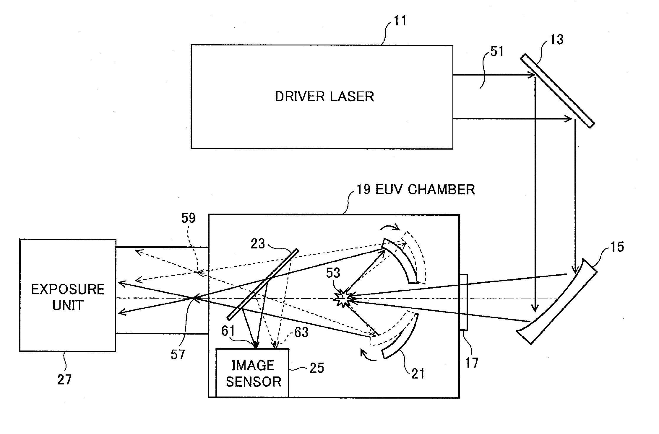
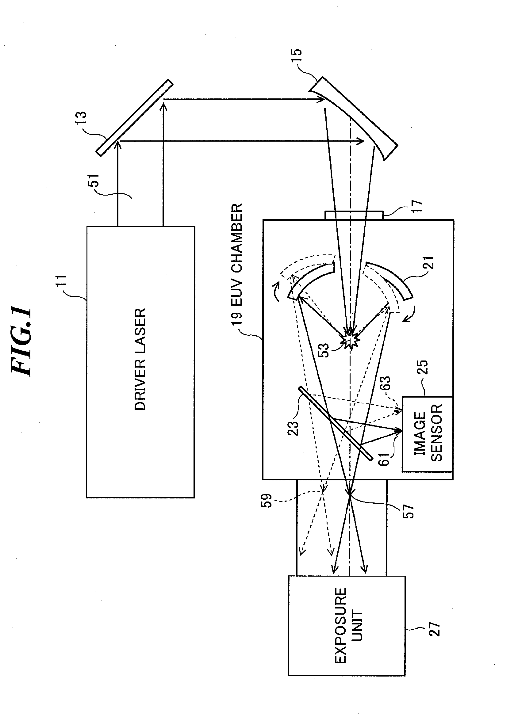
[0071]FIG. 1 is a schematic diagram showing a configuration of an EUV light source apparatus according to the first embodiment of the present invention. The EUV light source apparatus employs a laser produced plasma (LPP) type for generating EUV light by irradiating a target material with a laser beam to excite the target material.

[0072]As shown in FIG. 1, the EUV light source apparatus according to the embodiment includes a driver laser 11 for generating a laser beam 51 for irradiating and exciting the target material, a reflection mirror 13 and an off-axis parabolic mirror 15 forming a laser beam focusing optics for focusing the laser beam 51 on the target material, and an EUV chamber 19 in which EUV light is generated. The EUV light generated by the EUV light source apparatus is supplied to an exposure unit 27.

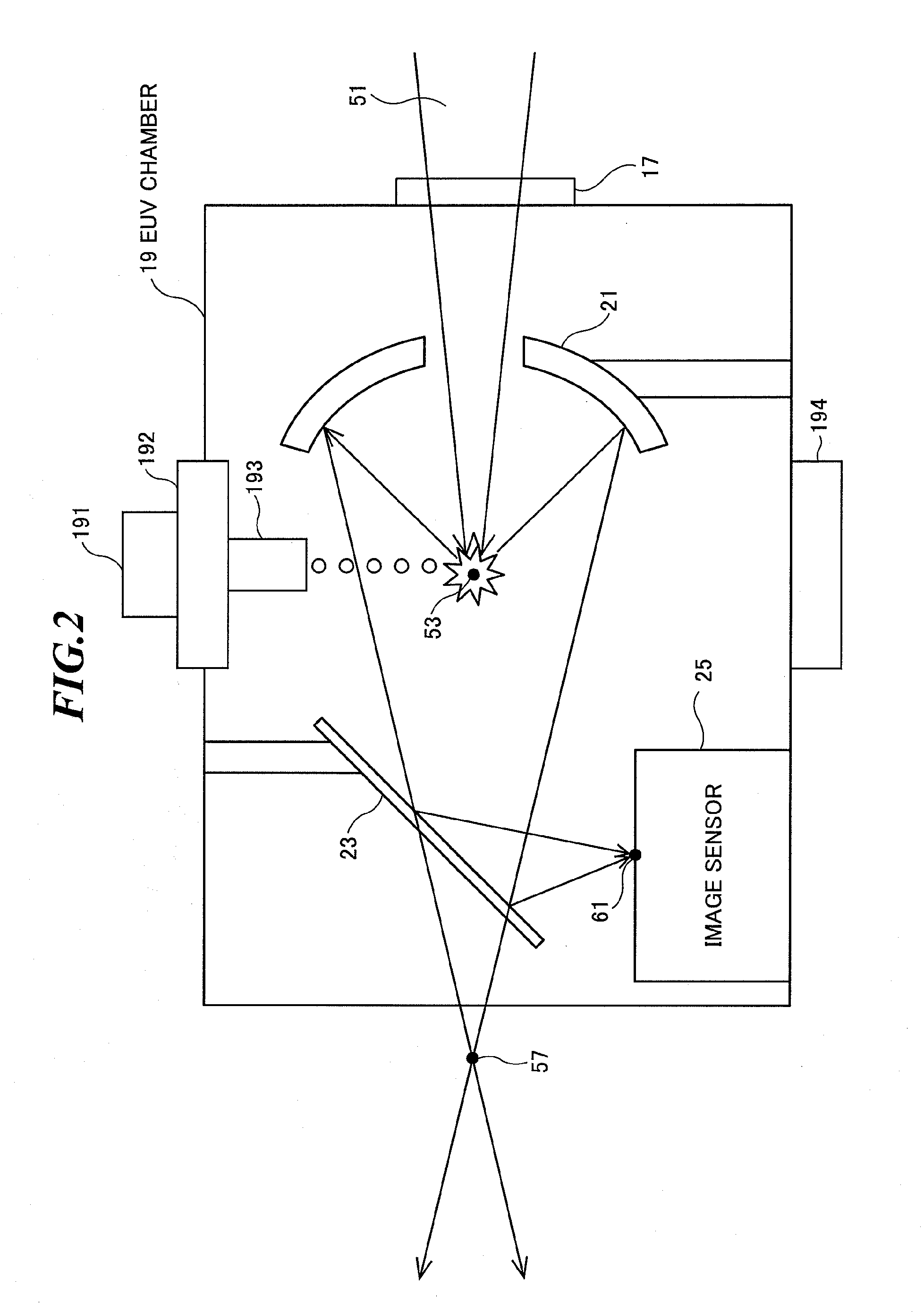
[0073]FIG. 2 is an enlarged view of the EUV chamber as shown in FIG. 1. In the EUV chamber 19, a target supply unit 191, a target location adjustment unit 192, a target noz...

embodiment 2

[0090]FIG. 5 is a schematic diagram showing a configuration of an EUV light source apparatus according to the second embodiment of the present invention. The EUV light source apparatus according to the second embodiment includes a feedback control system for the purpose of IF image stabilization in addition to the EUV light source apparatus according to the first embodiment. In the EUV light source apparatus as shown in FIG. 5, an EUV light source controller 31, an image sensor 35, an EUV collector mirror actuator 37, and an EUV collector mirror stage 39 are added to the EUV light source apparatus as shown in FIG. 1. Further, the EUV light source controller 31 transmits and receives signals between an exposure unit controller 33 attached to the exposure unit 27 and itself.

[0091]The light reflected by the splitter optical element 23 provided between the first focal point 53 and the second focal point 57 of the EUV collector mirror 21 forms an IF image at the third focal point 63, and...

embodiment 3

[0157]FIG. 24 is a schematic diagram showing a configuration of an EUV light source apparatus according to the third embodiment of the present invention. In order to adjust the location of the second focal point according to the light profile (location and / or shape) of the IF image at the third focal point, it is necessary that the location of the EUV light at the first focal point is stable. Accordingly, in the EUV light source apparatus according to the third embodiment, a control system for controlling the location of the droplets of the target material and a control system for controlling the location of the focusing point of the laser beam outputted from the driver laser are embodied, and the rest of the configuration is the same as that in the second embodiment.

[0158]As shown in FIG. 24, the EUV light source apparatus according to the third embodiment includes a droplet generating unit 71, a droplet catcher 73, a droplet location sensor 75, a droplet controller 77, a droplet a...


PUM


Abstract

An extreme ultraviolet (EUV) light source apparatus in which a location or posture shift of an EUV collector mirror can be detected. The apparatus includes: a chamber; a target supply mechanism for supplying a target material into the chamber; a driver laser for irradiating the target material with a laser beam to generate plasma; a collector mirror having a first focal point and a second focal point, for reflecting light, which is generated at the first focal point, toward the second focal point; a splitter optical element provided in an optical path of the light reflected by the collector mirror, for splitting a part of the light reflected by the collector mirror; and an image sensor provided in an optical path of the light split by the splitter optical element, for detecting a profile of the light split by the splitter optical element.

Description

CROSS-REFERENCE TO RELATED APPLICATION[0001]The present application claims priority from Japanese Patent Application No. 2008-274317 filed on Oct. 24, 2008, the contents of which are incorporated herein by reference in their entirety.BACKGROUND OF THE INVENTION[0002]1. Field of the Invention[0003]The present invention relates to an extreme ultraviolet (EUV) light source apparatus to be used as a light source of exposure equipment.[0004]2. Description of a Related Art[0005]In recent years, as semiconductor processes become finer, photolithography has been making rapid progress toward finer fabrication. In the next generation, micro-fabrication at 70 nm to 45 nm, further, micro-fabrication at 32 nm and beyond will be required. Accordingly, in order to fulfill the requirement for micro-fabrication at 32 nm and beyond, for example, exposure equipment is expected to be developed by combining an EUV light source for generating EUV light having a wavelength of about 13 nm and reduced proje...

Claims


Application Information

Patent Timeline
Patent Type & Authority Applications(United States)
IPC IPC(8): G21K5/00
CPCG03F7/70033G03F7/70141G03F7/70175G03F7/70191H05G2/005G03F7/70591G03F7/7085G03F7/70891G03F7/70575
Inventor SUGANUMA, TAKASHIMORIYA, MASATOABE, TAMOTSUKAKIZAKI, KOUJIWAKABAYASHI, OSAMU
Owner GIGAPHOTON
Why Eureka
Try Eureka