
Echelle grating with cyclic free-spectral range

a cyclic free-spectral range, optical device technology, applied in the field of optical devices, can solve the problems of reducing the size of the device, and not developing the wavelength division multiplexing filter (such as an optical de-mux), which can be used in wavelength division multiplexing (wdm), etc., to achieve the effect of eliminating spectral gaps and reducing the tuning energy of the optical devi

Active Publication Date: 2013-02-14
ORACLE INT CORP
View PDF4 Cites 4 Cited by
  • Summary
  • Abstract
  • Description
  • Claims
  • Application Information

AI Technical Summary

Benefits of technology

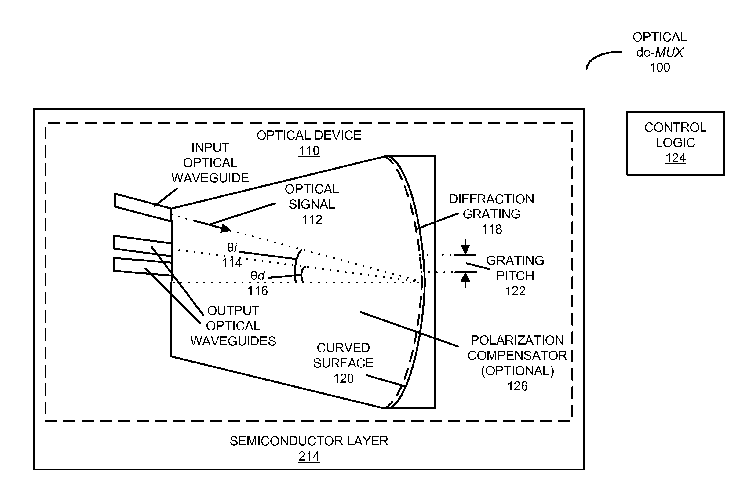
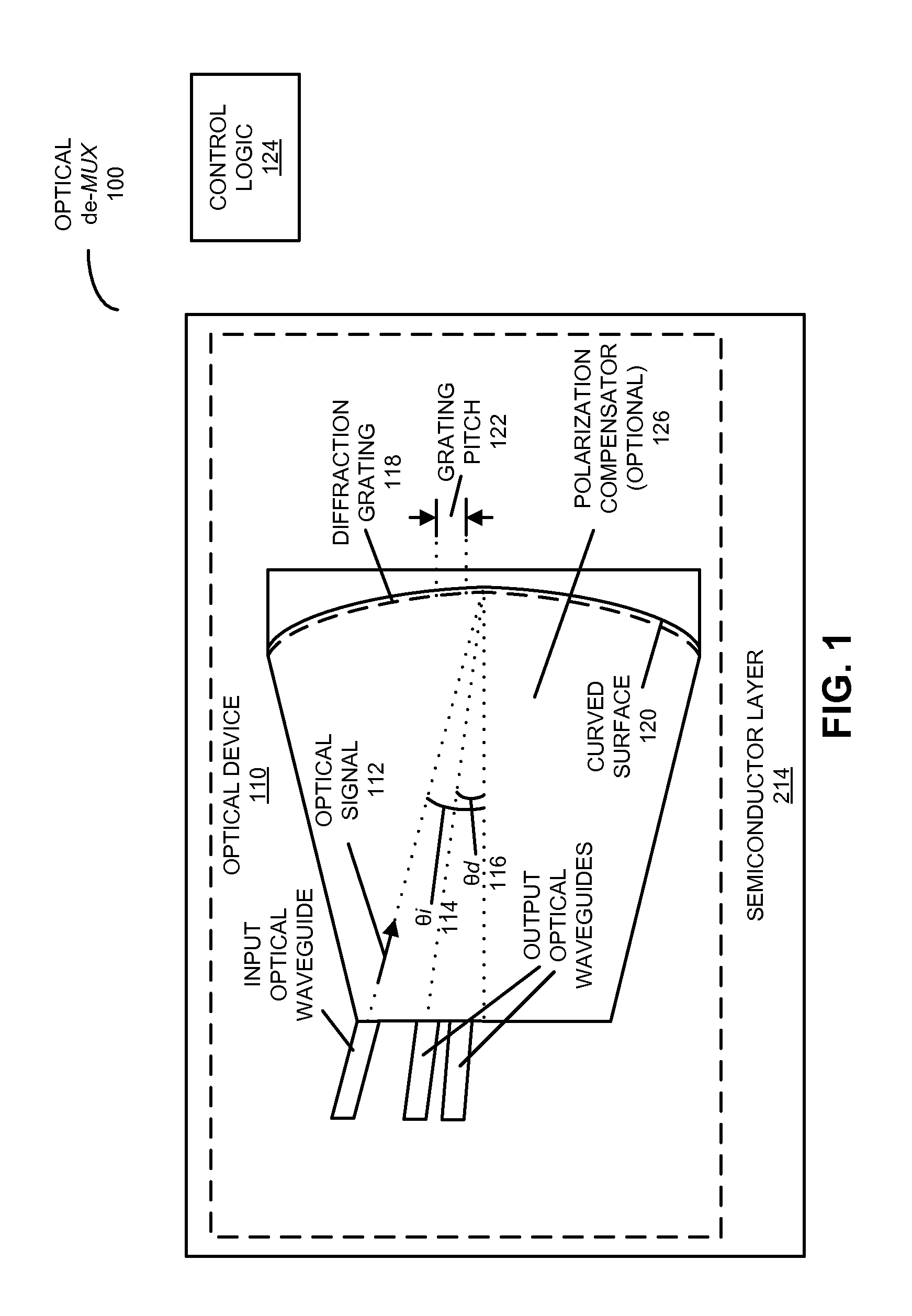
The present disclosure provides an optical de-multiplexer (de-MUX) that can resolve optical signals into different wavelength channels. The de-MUX has a special optical device that images and diffracts the optical signal using a reflective geometry, which causes the signal to be transmitted through the device with a specific arrangement of wavelength channels. This arrangement reduces the energy required for tuning the device and prevents the appearance of spectral gaps between channels. The de-MUX includes control logic that assigns a given carrier wavelength in the optical signal to a nearby wavelength channel, which compensates for any shift in the spectral locations of the channels. The received optical signal is then output from the de-MUX. This technology provides a more efficient way to multiplex and de-multiplex optical signals.

Problems solved by technology

However, a wavelength filter (such as an optical de-MUX), which can be used in wavelength division multiplexing (WDM), has not been developed yet.
However, echelle gratings are sensitive to non-vertical grating facets and facet roughness, which can result in optical crosstalk and on-chip insertion loss.
A disadvantage of this approach is that, with a very small diffraction angle, for a given linear dispersion, the focal length for the Rowland circle on which the output optical waveguides are arranged (and hence the size of the device) increases dramatically.
In particular, compared with echelle gratings with a typical diffraction angle, this arrangement of the output optical waveguides may increase the device size by a factor of 10, which increases the manufacturing cost and may limit applications in size-sensitive optical links.
However, in contrast with a thick SOI platform, the control of the center wavelength for an optical de-MUX implemented using a nano-photonic SOI platform can be extremely challenging because these devices are very sensitive to silicon thickness variation.
As a consequence, wavelength tuning may be needed to correct for manufacturing-induced phase errors to align the optical de-MUX spectrum with transmitter channels, but this large tuning range may limit applications in energy-sensitive optical interconnects.

Method used


Image

  • Echelle grating with cyclic free-spectral range
  • Echelle grating with cyclic free-spectral range
  • Echelle grating with cyclic free-spectral range

Examples


Embodiment Construction

[0028]Embodiments of an optical de-multiplexer (de-MUX), a system that includes the optical de-MUX, and a method for de-multiplexing an optical signal are described. This optical de-MUX includes an optical device that images and diffracts the optical signal using a reflective geometry, where a free spectral range (FSR) of the optical device associated with a given diffraction order abuts FSRs associated with adjacent diffraction orders (which is sometimes referred to as a ‘cyclic FSR’). Moreover, the channel spacings within diffraction orders and between adjacent diffraction orders are equal to the predefined channel spacing associated with the optical signal (e.g., the FSR equals the number of channels times the channel spacing). As a consequence, the optical device has a comb-filter output spectrum, which reduces a tuning energy of the optical device by eliminating spectral gaps between diffraction orders of the optical device.

[0029]By providing a cyclic FSR, the optical de-MUX ca...


PUM


Abstract

An optical de-multiplexer (de-MUX) that includes an optical device that images and diffracts an optical signal using a reflective geometry is described, where a free spectral range (FSR) of the optical device associated with a given diffraction order abuts FSRs associated with adjacent diffraction orders. Moreover, the channel spacings within diffraction orders and between adjacent diffraction orders are equal to the predefined channel spacing associated with the optical signal. As a consequence, the optical device has a comb-filter output spectrum, which reduces a tuning energy of the optical device by eliminating spectral gaps between diffraction orders of the optical device.

Description

GOVERNMENT LICENSE RIGHTS[0001]This invention was made with Government support under Agreement No. HR0011-08-9-0001 awarded by DARPA. The Government has certain rights in the invention.BACKGROUND[0002]1. Field[0003]The present disclosure generally relates to optical devices. More specifically, the present disclosure relates to an optical de-multiplexer (de-MUX) that includes an echelle grating having a cyclic free-spectral range (FSR).[0004]2. Related Art[0005]Integrated silicon photonics is a promising new technology that provides a number of advantages for chip-level communication, such as very high index contrast and compatibility with CMOS fabrication technology. Ongoing research into integrated silicon photonics is focusing on opportunities to provide low latency, high bandwidth, high density, and low power consumption. To date, several key active elements, including silicon lasers, modulators, and photodetectors, have been realized in silicon using low-cost CMOS compatible pro...

Claims


Application Information

Patent Timeline
IPC IPC(8): H04J14/02G02B5/18
CPCH04J14/02G02B6/2931G02B6/29308
Inventor LUO, YINGZHENG, XUEZHELI, GUOLIANGRAJ, KANNANKRISHNAMOORTHY, ASHOK V.
Owner ORACLE INT CORP
Learn More