Method to determine a predetermined signal amplitude in mr measurements

a predetermined signal and measurement method technology, applied in the direction of geological measurements, reradiation, sensors, etc., can solve the problems of not being accepted for use in excitation and refocusing of magnetization in imaging sequences, etc., to achieve the effect of reducing b1-dependent magnetic field inhomogeneities and artifacts

Inactive Publication Date: 2010-06-10
SIEMENS HEALTHCARE GMBH
View PDF23 Cites 21 Cited by
  • Summary
  • Abstract
  • Description
  • Claims
  • Application Information

AI Technical Summary

Benefits of technology

[0013]An object of the present invention is to further reduce the B1-dependent magnetic f...

Problems solved by technology

With conventional methods it is not possible to directly affect the B1 homogeneity of RF fields, such that conventional methods are largely based on being made as insensitive as possible to the B1 inhomogeneity.
For example, composite pulses and adiabatic pulses are used, but these pulses have a limited applicability with regard to achievable flip angles, phase response in the use for slice selection, pulse times and the absorption rate given the radiation of RF power into a body.
For this reason, such pulses are typically used for the preparation of the magnetization but could not become accepted for use in the excitation and refocusing of the magnetization in imaging sequences.
However, the achievable pulse times are always still too long, such that they cannot ...

Method used


Image

  • Method to determine a predetermined signal amplitude in mr measurements
  • Method to determine a predetermined signal amplitude in mr measurements
  • Method to determine a predetermined signal amplitude in mr measurements

Examples


Embodiment Construction

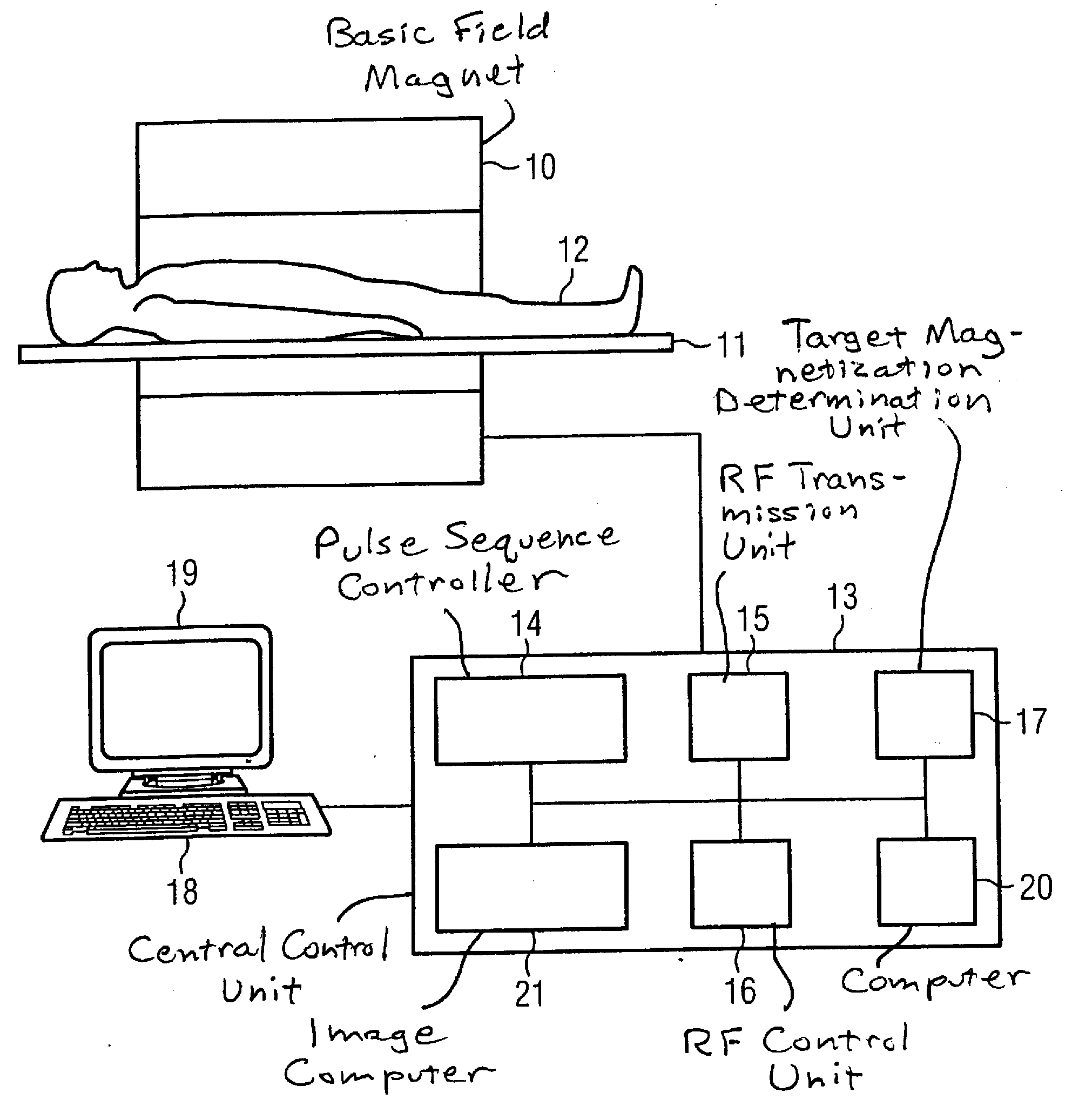
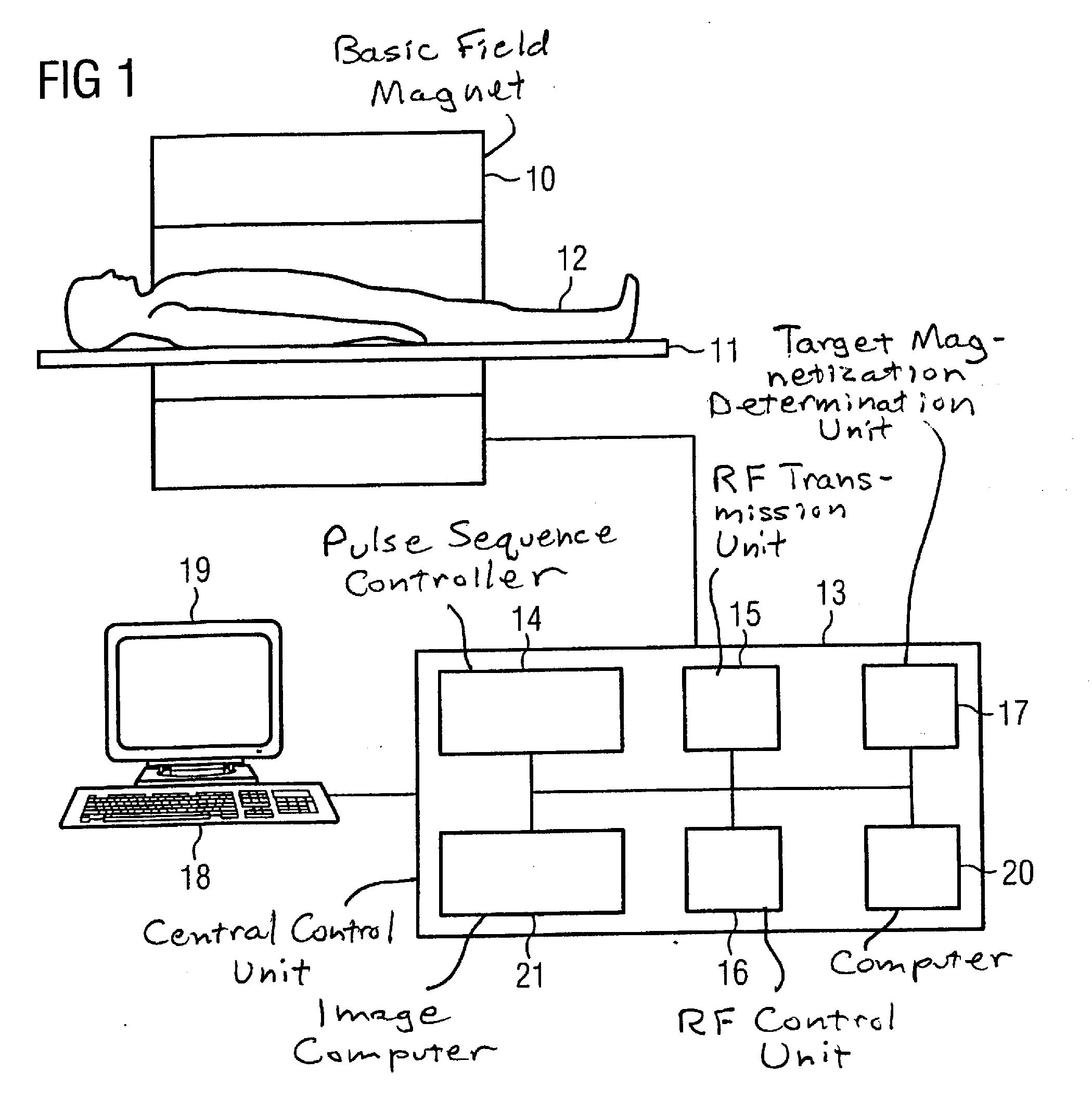
[0034]An MR system according to the invention is presented in FIG. 1. This MR system has a basic field magnet 10 for the generation of a polarization field B0. An examination subject 12 arranged on the bed 11 is driven into the isocenter of the magnet in order to generate MR images there via radiation of RF pulses and gradient fields. The manner by which MR images can be generated with such a pulse series of RF pulses to excite the given magnetization and via simultaneous switching of magnetic field gradients is known to those skilled in the art and need not be explained in detail herein. The MR system is connected with a central control unit 13 with which the workflow of an MR examination can be controlled. The control unit 13 can have a pulse sequence controller 14 that controls the workflow when RF pulses and gradient fields must be generated. An RF transmission unit 15 is likewise provided that advantageously possesses multiple RF transmission channels that can be individually c...


PUM


Abstract

In a method and apparatus to determine a predetermined signal amplitude of an examination subject in an MR measurement in which multiple RF pulses are radiated into the examination subject in a pulse sequence in a pulse series with a repetition time TR that is smaller than the T2 times of the examination subject, a target magnetization is established for a predetermined point in time after radiation of the respective RF pulse for essentially all RF pulses from the pulse series, a target flip angle and a target phase are determined for different regions of the examination subject for essentially all RF pulses depending on the respective target magnetization, a respective amplitude and phase response is determined for essentially all RF pulses to generate the respective target magnetization after radiation of the respective RF pulse, and the RF pulses with the respective determined amplitude and phase response are radiated into the examination subject.

Description

BACKGROUND OF THE INVENTION[0001]1. Field of the Invention[0002]The present invention concerns a method to determine a predetermined signal amplitude of an examination subject in a magnetic resonance measurement in which, given a pulse sequence, multiple RF pulses are radiated into an examination subject in a pulse series; the invention also concerns an MR system for this. The invention is particularly suitable to reduce spatial image inhomogeneities in MR exposures that are caused by the spatial variation of the RF field distribution in the examination subject.[0003]2. Description of the Prior Art[0004]In whole-body imaging, artifacts occur in the image in MR systems, particularly with systems employing high field strengths (for example 3 Tesla), which has previously prevented a wider prevalence of such examinations. These image artifacts are reinforced with the increase of the field strength B0 that is used. They occur increasingly at even higher field strengths and also increasin...

Claims


Application Information

Patent Timeline
IPC IPC(8): G01R33/44
CPCG01R33/246G01R33/583G01R33/543
Inventor FAUTZ, HANS-PETERSCHMITT, FRANZ
Owner SIEMENS HEALTHCARE GMBH
Why Eureka
Try Eureka