System, apparatus and method for extracting three-dimensional information of an object from received electromagnetic radiation

a technology of electromagnetic radiation and three-dimensional information, applied in the field of system, apparatus and method for extracting three-dimensional information of an object from received electromagnetic radiation, can solve the problems of low resolution or low fidelity of three-dimensional images of poor quality

Active Publication Date: 2010-06-10
CELLOPTIC
View PDF4 Cites 105 Cited by
  • Summary
  • Abstract
  • Description
  • Claims
  • Application Information

AI Technical Summary

Benefits of technology

[0029]Another object of this invention is to provide a novel apparatus, wherein a predetermined thickness and coefficients of absorption or reflectance of the electromagnetic radiation assembly is configured to control the phase and intensity of the diffracted light.
[0030]Another objec...

Problems solved by technology

However, conventional techniques may disadvantageously require an active illumination source, or place limitations on a light source (e.g., may require coherent light, a point light source or a bandwidth limited light), place limitations on movement of the object or the sensing apparatus (e.g., require...

Method used


Image

  • System, apparatus and method for extracting three-dimensional information of an object from received electromagnetic radiation
  • System, apparatus and method for extracting three-dimensional information of an object from received electromagnetic radiation
  • System, apparatus and method for extracting three-dimensional information of an object from received electromagnetic radiation

Examples


Embodiment Construction

[0137]Conventional holographic techniques may include methods of capturing a hologram of an object by capturing an interference pattern that results when a first portion of a coherent laser light beam (e.g., reference beam) interferes with a second portion of the laser light beam reflected off the object (e.g., object beam). A three-dimensional image of the object may be viewed by appropriately illuminating the recorded interference pattern with the reference beam.

[0138]FIG. 32 is a block diagram of a conventional holographic system including a laser 9000 that shines a coherent laser light beam along a first optical axis 9026 through a partially reflective and transmissive mirror, such as a beam splitter 9002. A first portion of the split laser beam is guided by lens 9004 and mirror 9008 to illuminate the object 9014 with the object beam 9010 along a second optical axis 9024. A second portion of the split laser beam is reflected by the beamsplitter 9002 along a third optical axis 90...


PUM


Abstract

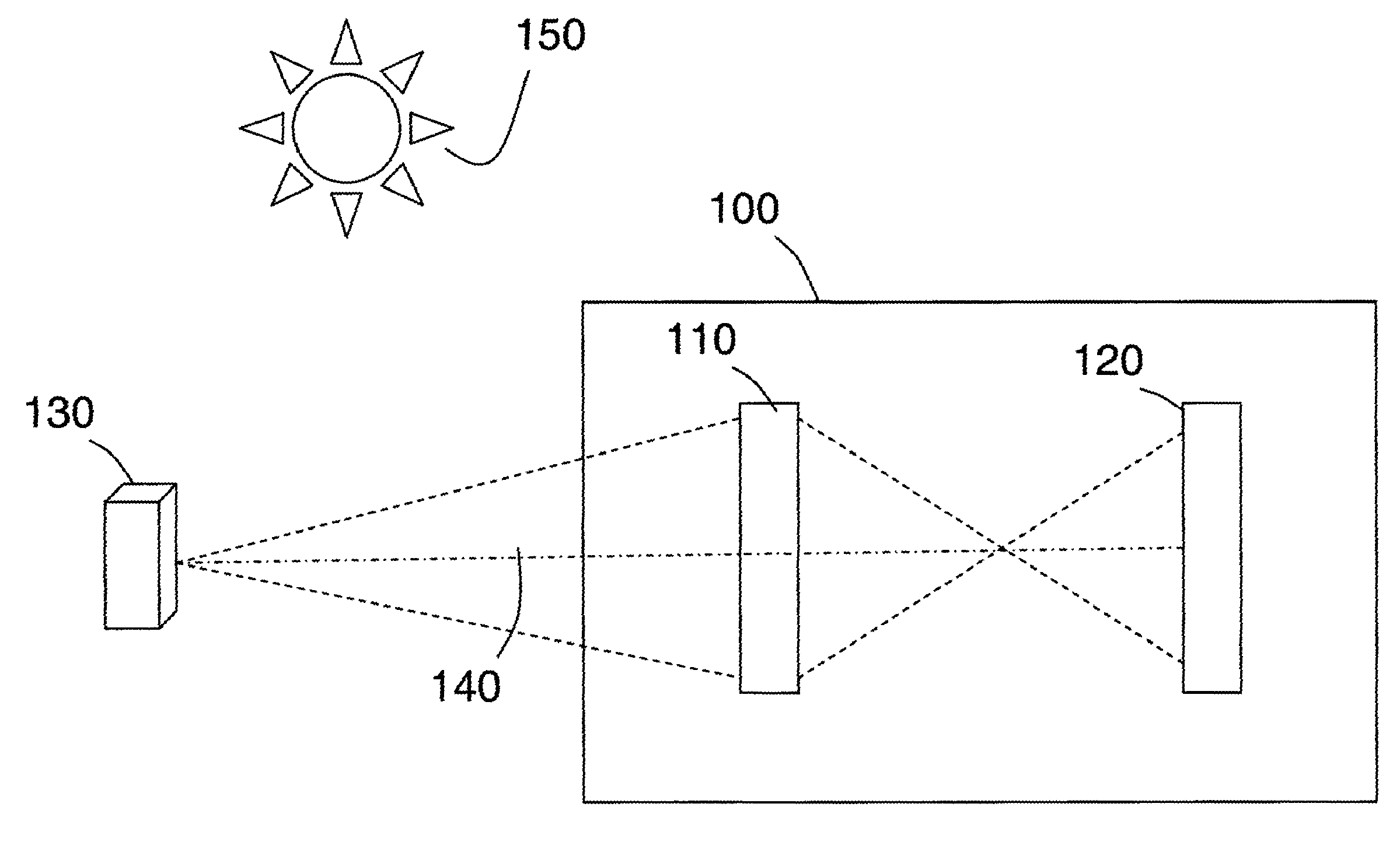
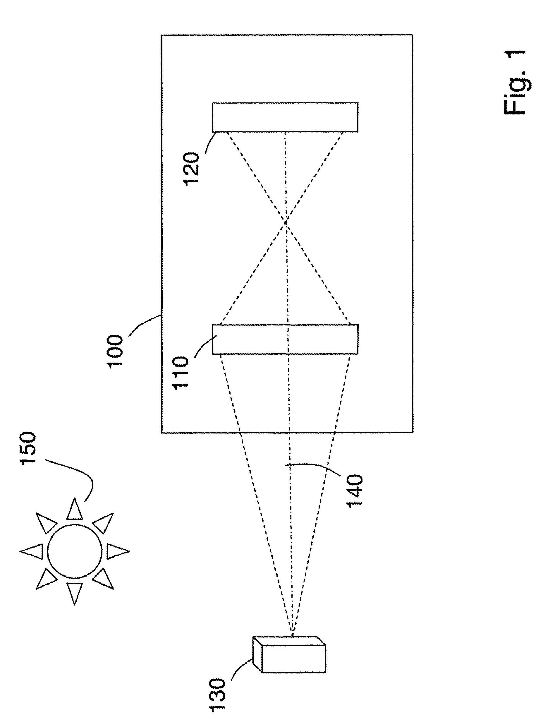
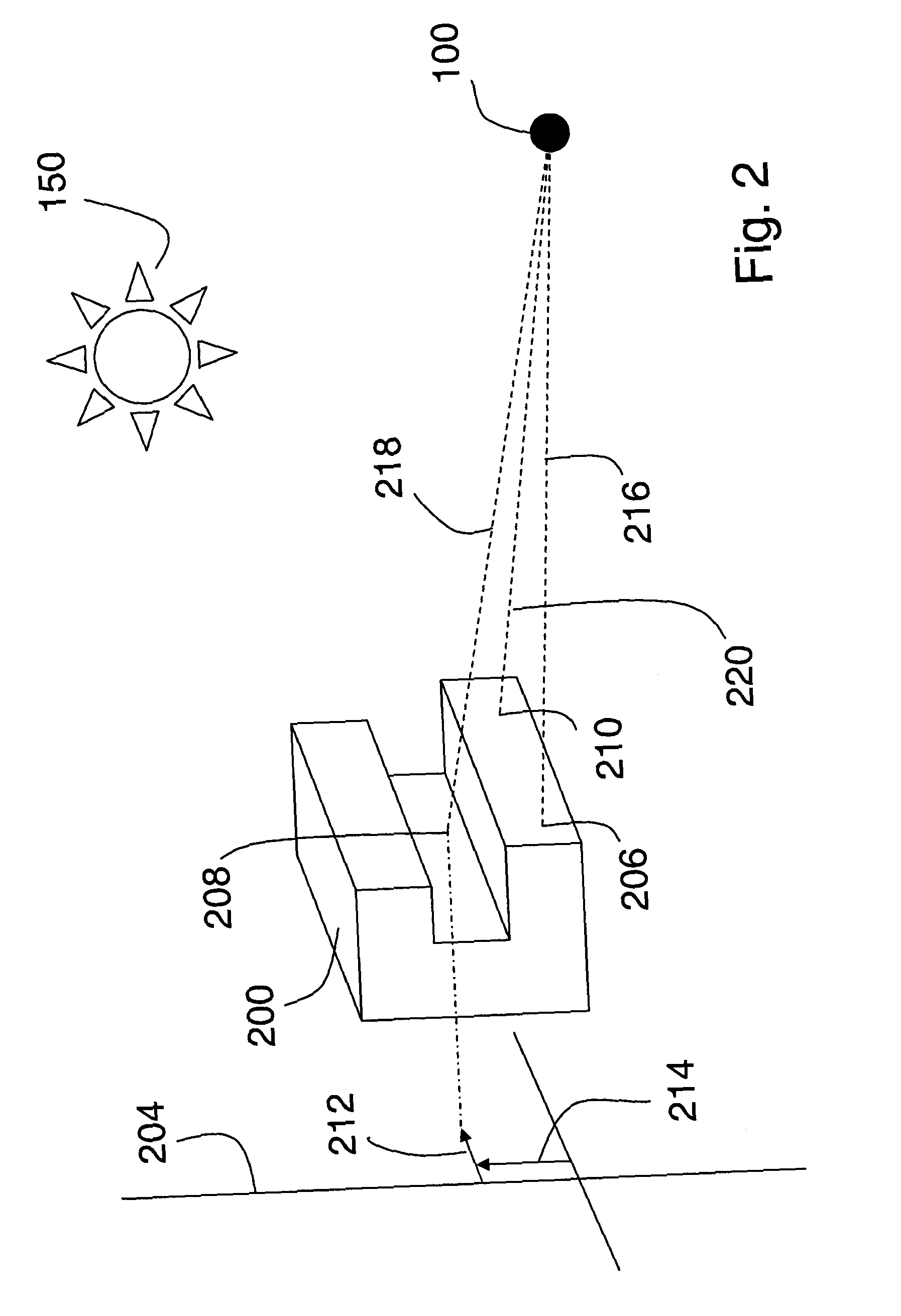
An apparatus and method to produce a hologram of an object includes an electromagnetic radiation assembly configured to receive a received electromagnetic radiation, such as light, from the object. The electromagnetic radiation assembly is further configured to diffract the received electromagnetic radiation and transmit a diffracted electromagnetic radiation. An image capture assembly is configured to capture an image of the diffracted electromagnetic radiation and produce the hologram of the object from the captured image.

Description

CROSS REFERENCE TO RELATED APPLICATIONS[0001]This application is related to co-pending PCT / US06 / 27727, filed Jul. 18, 2006, U.S. Patent Provisional Application No. 60 / 866,358, filed Nov. 17, 2006, and U.S. Patent Provisional Application No. 60 / 869,022, filed Dec. 7, 2006, and claims priority to U.S. Patent Provisional Application No. 60 / 866,358 and U.S. Patent Provisional Application No. 60 / 869,022. The contents of these applications are incorporated herein by reference in their entirety.BACKGROUND OF THE INVENTION[0002]1. Field of the Invention[0003]This invention relates to an apparatus for capturing electromagnetic radiation, such as light or other forms of electromagnetic radiation, from an object and extracting object geometric information from the received radiation, in the field of three-dimensional imaging and holography. The invention also relates to a system and method of performing those functions.[0004]2. Discussion of the Background[0005]Conventional techniques for capt...

Claims


Application Information

Patent Timeline
IPC IPC(8): G03H1/04
CPCG03B35/02G03H1/0402H04N1/00827G03H2001/0224G03H2001/0458G03H2223/23G03H1/0443G03H1/041G03H2225/33G03H2240/13G03H2240/21G03H2240/23G03H2240/24G03H2001/0452G03H1/06G03H1/08G03H1/0841G03H2001/0436G03H2001/085
Inventor ROSEN, JOSEPHBROOKER, GARY
Owner CELLOPTIC
Why Eureka
Try Eureka