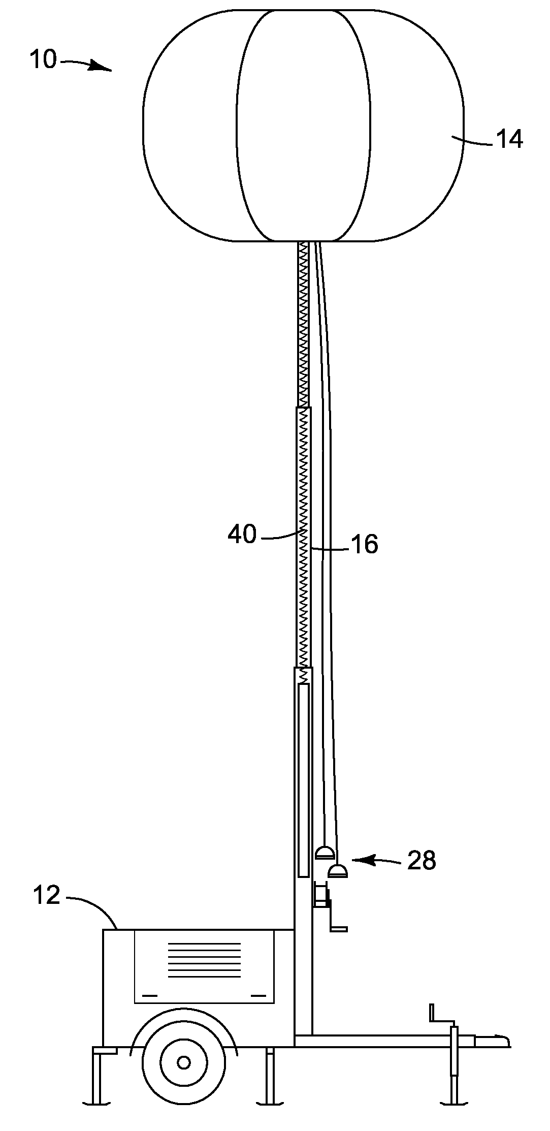
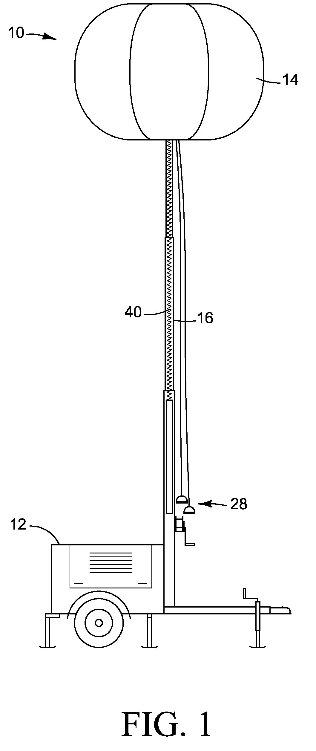
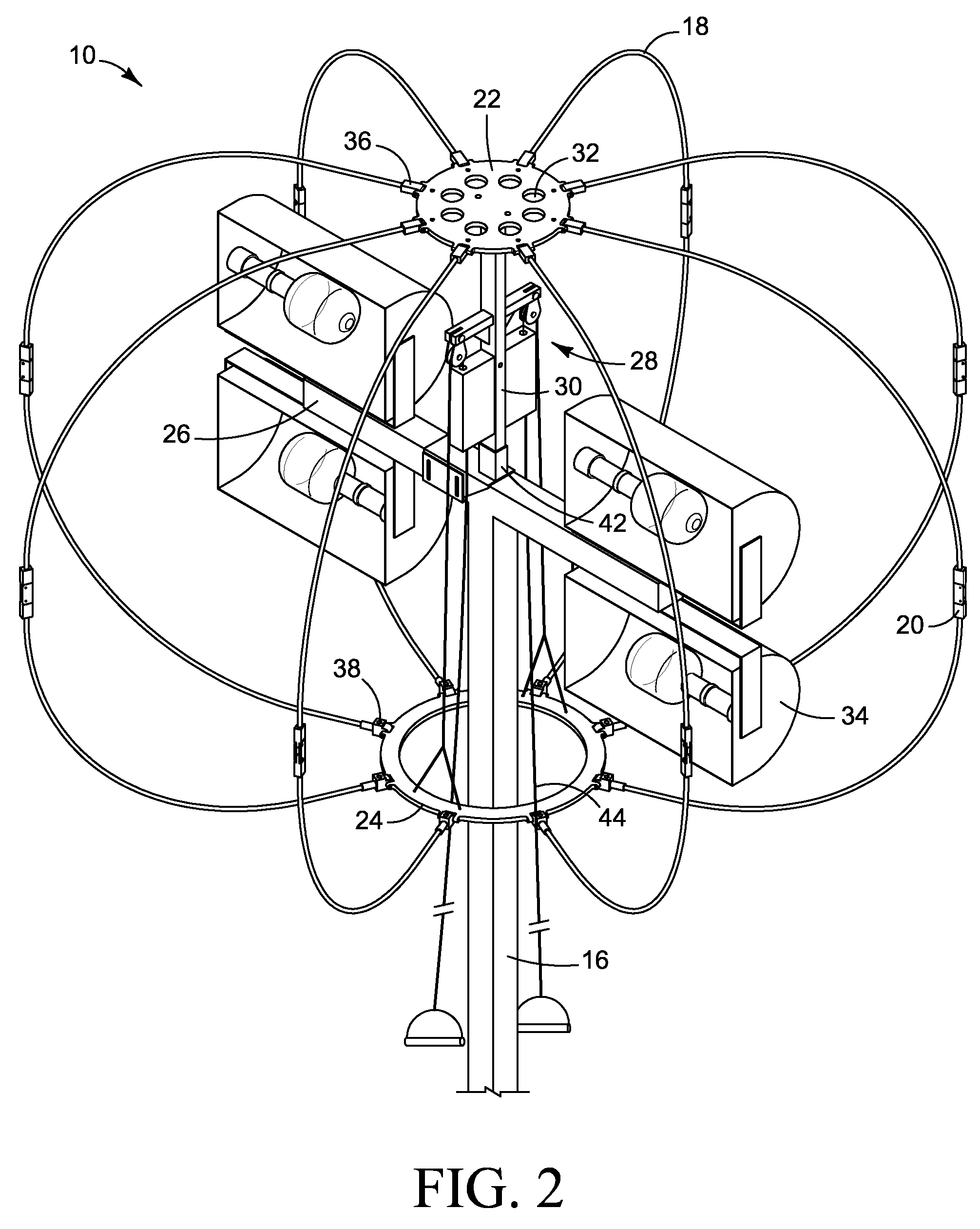
However, although the lights provide sufficient light to work under, these lights are typically very bright and create problems when workers or others look up into the lights.
This can be very hazardous to workers who are, for example but not limited to, operating a vehicle or working on scaffolding.
When the workers look up into the
bright light there exists a possibility that they can be temporarily blinded,
crash a vehicle, or perform an action that leads to injury.
A motorist passing by the
bright light of the light tower may be temporarily blinded or become fixated on the bright lights and fail to pay attention to the road or not be able to see the road.
Another problem with the bright, undiffused lights is that they create shadows on the work area.
As workers are often required to work in a variety of positions, often times with their backs to the light tower, they create a variety of shadows that can severely inhibit their
work productivity and lead to serious safety concerns.
For example, a worker faces a difficult situation when he needs to perform a task but his only possible
body position would be facing away from the light tower.
Consequently, his body casts a dark shadow over the area where he is working and he runs a much higher risk of injury as he cannot adequately view the work area.
Glare can also present a problem in work environments.
The bright light emitted by the light tower can glare off of
reflective surfaces and interfere with work operations.
An example is when glare from the light of a light tower is picked up by a camera and interferes with the scene recorded by the camera.
A further problem is that as light towers are often very bright for illuminating large areas, large bulbs are used that can create copious amounts of heat.
As current light diffusers do not use sufficient ventilation to allow air circulation, heat builds up in the light diffusers and can cause damage to the
electrical equipment of the light tower or even cause the light diffuser to ignite.
Additionally, this can make the equipment very difficult to maintain, to repair, or even to replace malfunctioning lights unless the tower is turned off and allowed to cool.
Another problem facing portable light towers and light diffusers is that often times the light diffuser does not have sufficient structure in order to prevent the light diffuser from coming into contact with the light.
This can lead to a fire as the lights can be very hot and can ignite the light diffusing material of the light diffuser.
Additionally, without an adequate underlying structure the light diffuser is expanded as long as air is forced into, or sealed within the diffuser envelope.
If the light diffuser deflates, it can also come into contact with the often hot lights and ignite, or burn the diffuser material.
However, these attempts have not solved the problem as they still often use an air
system with
forced air to maintain an inflated
balloon or an envelope that still uses a forced or sealed air supply to stay inflated.
Consequently, this requires an additional expenditure of energy to run the pump or fan making the light tower less efficient to operate.
In addition to the previous difficulties, current light towers also are not easily transportable when they are attached to a light diffuser or even when not attached to a light diffuser.
When the light diffusers are removed from the light towers they are often very large and bulky making them awkward to transport alone as well as when attached to a light tower.
Additionally, it is very difficult to remove the light diffusers from the light towers without completely disassembling the light tower diffuser.
This leads to an increased amount of time spent assembling and disassembling the light diffusers.
Consequently, the
overall efficiency of the worksite decreases as it takes workers more time to assemble and disassemble the diffuser while other workers may have to wait additional time until they have adequate light in which to work.
When a large light diffuser is left fully assembled to the telescoping tower, it is very difficult to transport because the light diffuser is very bulky.
Furthermore, when the light diffuser is fully assembled on the light tower while in transit, the light diffuser presents a significant amount of wind resistance as it is big and bulky.
In this situation, the light diffuser is much more prone to damage from
flying debris, inclement weather, and acts of vandalism if it is left fully attached to the portable light tower while in transit.
Accordingly, the
rigid frame is not flexible nor does it appear to provide a support structure for the
balloon or envelope which is likely supported by air sucked in through the intake.
Additionally, the frame apparently does not provide a means for quickly closing or opening the light diffuser.
As the
balloon likely relies on an air supply creating pressure within the balloon to remain inflated, it may not provide sufficient openings in order to allow air circulation for cooling the lights.
In addition to the aforementioned problems, it appears that of the diffusers known in the art apparently no diffuser presents an easily disassembled or easily deployed light diffuser.


