X-ray diagnosis apparatus and image processing apparatus

Active Publication Date: 2010-06-10
KK TOSHIBA +1
View PDF5 Cites 18 Cited by
  • Summary
  • Abstract
  • Description
  • Claims
  • Application Information

AI Technical Summary

Problems solved by technology

However, in the intravascular interventional treatment, the treatment time may be long, so that an X-ray image (fluoroscopic image) is radiographed with the minimum X-ray dose to be radiated to a patient.
Therefore, noise increases on an X-ray image to be seen by a doctor.
The above de

Method used


Image

  • X-ray diagnosis apparatus and image processing apparatus
  • X-ray diagnosis apparatus and image processing apparatus
  • X-ray diagnosis apparatus and image processing apparatus

Examples


first embodiment

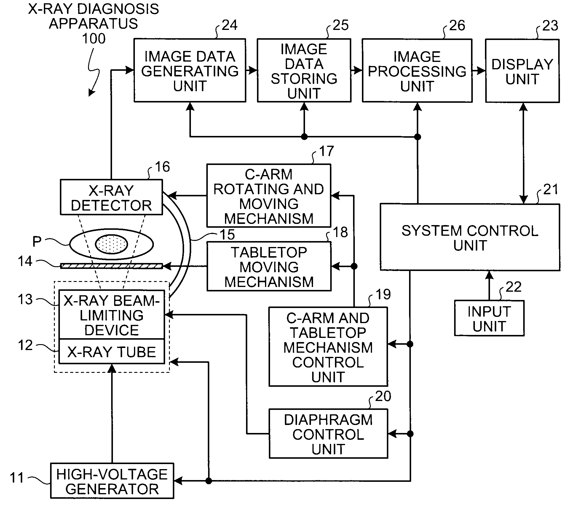
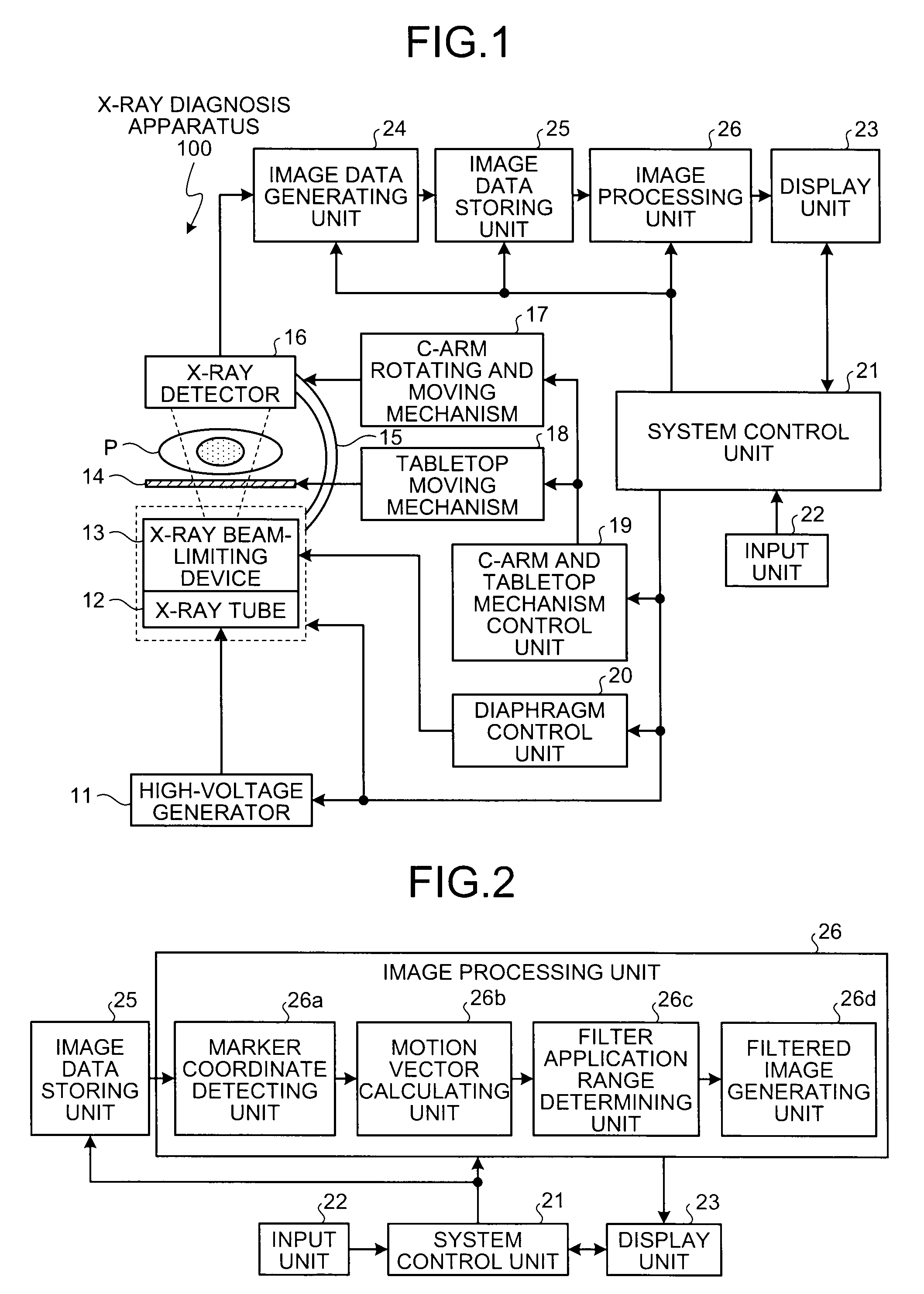
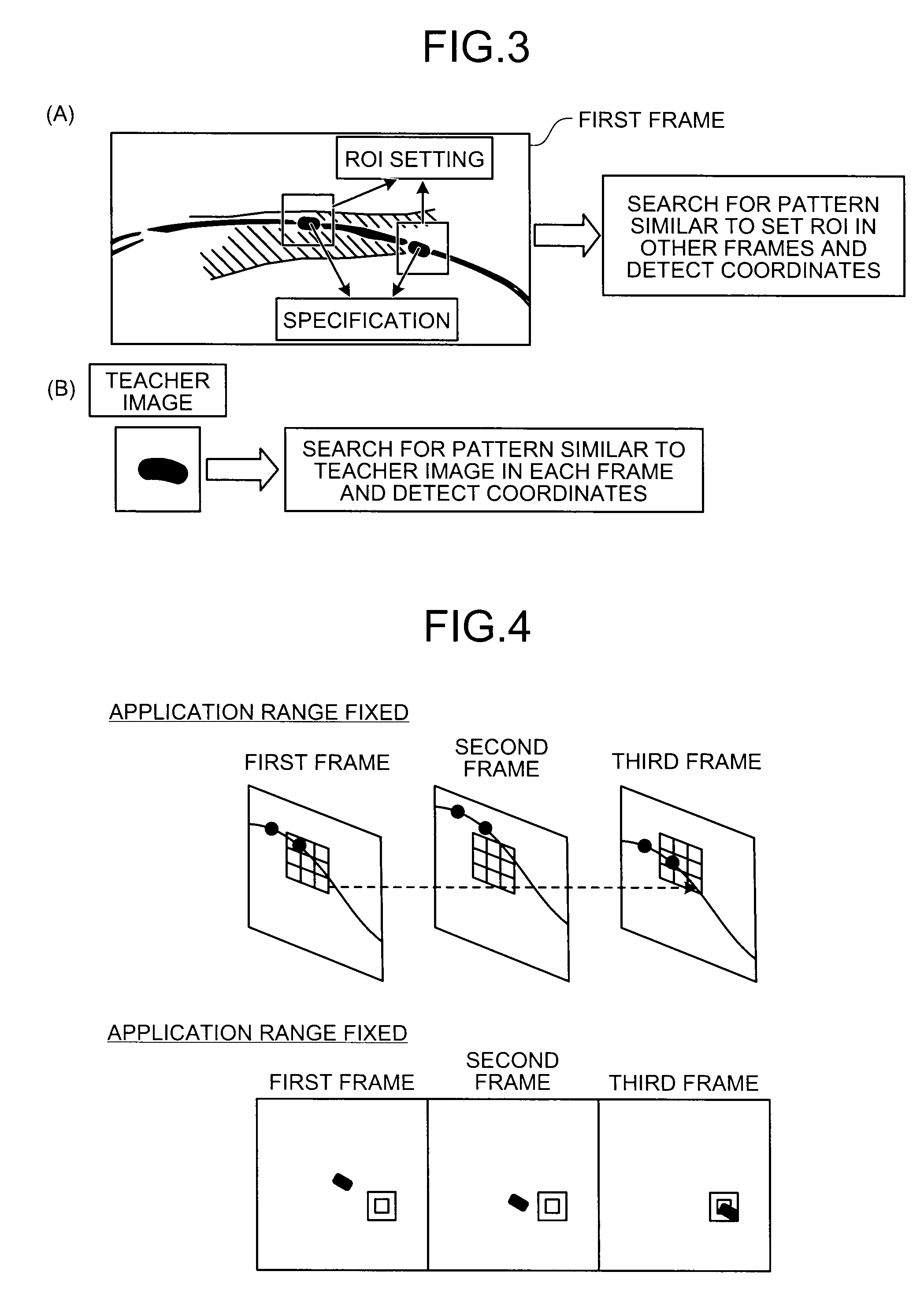
[0042]The X-ray diagnosis apparatus 100 in the present embodiment is mainly characterized in that the noise reducing effect by the smoothing filter can be always ensured by performing a process by the image processing unit 26 that is explained in detail below with reference to FIG. 2 to FIG. 5. FIG. 2 is a diagram for explaining a configuration of an image processing unit FIG. 3 is a diagram for explaining a marker coordinate detecting unit, and FIGS. 4 and 5 are diagrams for explaining a filter application range determining unit.

[0043]As shown in FIG. 2, the image processing unit 26 includes a marker coordinate detecting unit 26a, a motion vector calculating unit 26b, a filter application range determining unit 26c, and a filtered image generating unit 26d.

[0044]The marker coordinate detecting unit 26a detects coordinates of the stent markers attached to the balloon of the stent with the balloon for each of a plurality of X-ray images (fluoroscopic images) in a time sequence stor...

second embodiment

[0076]The marker coordinate detecting unit 26a in the second embodiment performs the process of detecting the coordinates of the stent markers on the high-frequency component image separated from an original image by the frequency component separating unit 26e.

[0077]The motion vector calculating unit 26b in the second embodiment performs the process of calculating the motion vector by using the coordinates of the stent markers in the high-frequency component image detected by the marker coordinate detecting unit 26a. In other words, the motion vector calculating unit 26b in the second embodiment calculates, with the coordinates of the stent markers detected in the high-frequency component image in the first frame as the reference coordinates, the motion vector of the coordinates of the stent markers detected in each high-frequency component image in the second and subsequent frames with respect to the reference coordinates.

[0078]The filter application range determining unit 26c in ...

third embodiment

[0090]The filtered image generating unit 26d in the third embodiment performs the noise reducing process using a spatial filter described in “Nambu K, Iseki H. A noise reduction method based on a statistical test of high dimensional pixel vectors for dynamic and volumetric images. Riv Neuroradiol 2005; 18:21-33.” and “Nishiki, Method for reducing noise in X-ray images by averaging pixels based on the normalized difference with the relevant pixel, Radiological Physics and Technology, Vol 2, 2008” after the application range determining process by the filter application range determining unit 26c is performed.

[0091]Specifically, the filtered image generating unit 26d calculates the difference value between each pixel in the process target image and pixels in a predetermined range in a spatial direction by using pixel values of pixels corresponding to the process target image in the application range of the reference image. Then, the filtered image generating unit 26d newly calculates ...


PUM


Abstract

When a plurality of X-ray images in a time sequence is stored in an image data storing unit (25), a marker coordinate detecting unit (26a) detects coordinates of a stent marker in each X-ray image, and a motion vector calculating unit (26b) calculates, with coordinates of the stent marker detected in a first frame as reference coordinates, a motion vector of the coordinates of the stent marker detected in each X-ray image of a second and subsequent frames with respect to the reference coordinates. Then, a filter application range determining unit (26c) moves and determines an application range of a smoothing filter in each X-ray image based on the motion vector, and the filtered image generating unit (26d) generates a filtered image by performing a process by the smoothing filter between application ranges determined in a process target image and a reference image.

Description

CROSS-REFERENCE TO RELATED APPLICATIONS[0001]This application is based upon and claims the benefit of priority from the prior Japanese Patent Application No. 2008-311267, filed on Dec. 5, 2008; the entire contents of which are incorporated herein by reference.BACKGROUND OF THE INVENTION[0002]1. Field of the Invention[0003]The present invention relates to an X-ray diagnosis apparatus and an image processing apparatus[0004]2. Description of the Related Art[0005]Conventionally, a smoothing filter such as a recursive filter that performs a smoothing process between a plurality of frames in a time sequence is widely used as a method for reducing noise in an X-ray image.[0006]Specifically, the recursive filter is a filter that reduces high frequency noise by adding pixel values of pixels constituting a past frame on which a predetermined weighting is performed to pixel values of pixels constituting a frame as a process target (for example, see JP-A 2007-330522 (KOKAI)).[0007]Moreover, rec...

Claims


Application Information

Patent Timeline
IPC IPC(8): G06K9/62
CPCA61B6/00G06T5/20G06T7/0042G06T2207/10116G06T2207/30048A61B6/03G06T2207/30101G06T5/002G06T5/50G06T2207/10016G06T2207/30052G06T7/73
Inventor SAKAGUCHI, TAKUYASHIRAISHI, KUNIONISHIKI, MASAYUKINAMBU, KYOJIRO
Owner KK TOSHIBA
Why Eureka
Try Eureka