Enhanced relief printing plate

a printing plate and relief technology, applied in the field of relief printing, can solve the problems of less accurate features and the challenge of accurate representation of halftone relief features throughout the tonal range, and achieve the effect of good image accuracy and dynamic rang

Active Publication Date: 2010-06-10
MIRACLON CORP
View PDF13 Cites 61 Cited by
  • Summary
  • Abstract
  • Description
  • Claims
  • Application Information

AI Technical Summary

Benefits of technology

[0013]The present invention provides a system and method for producing a relief image article that, when used in a printing process, produces a printed image with good image accuracy, dynamic range, ink density uniformity, and tonal linearity.
[0014]According to one aspect of the invention, a pattern can be applied to substantially all image feature sizes of the halftone image data to reduce the transparency of image areas of a mask by a constant amount. The resultant mask can be affixed to a plate precursor to form an intimate contact with, and a gaseous barrier to, the plate precursor. The plate precursor can then be exposed to curing radiation and the mask removed. After processing, the precursor forms a relief plate carrying a relief image that resolves the pattern in the surface of relief features. Solid ink densities are substantially maintained or increased when the pattern is applied to solid relief features.

Problems solved by technology

A number of challenges exist in preparing and printing with relief plates.
One challenge is to produce relief features that accurately represent image features.
Another challenge is to transfer an optimal quantity of ink from relief features so that printed ink densities on the substrate have a wide range and relatively linear correlation with image tonality.
Another challenge is to transfer ink with a uniform density to the substrate so that areas representing a specific image tonality have a consistent appearance.
In the presence of oxygen, some plate precursor materials require higher exposure levels to cure and thus image features can shrink in size, resulting in less accurate features.
For example, accurate representation of halftone relief features throughout the tonal range is still a challenge.

Method used


Image

  • Enhanced relief printing plate
  • Enhanced relief printing plate
  • Enhanced relief printing plate

Examples


Embodiment Construction

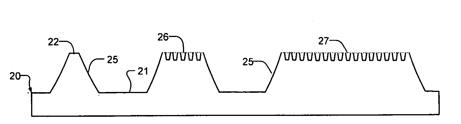
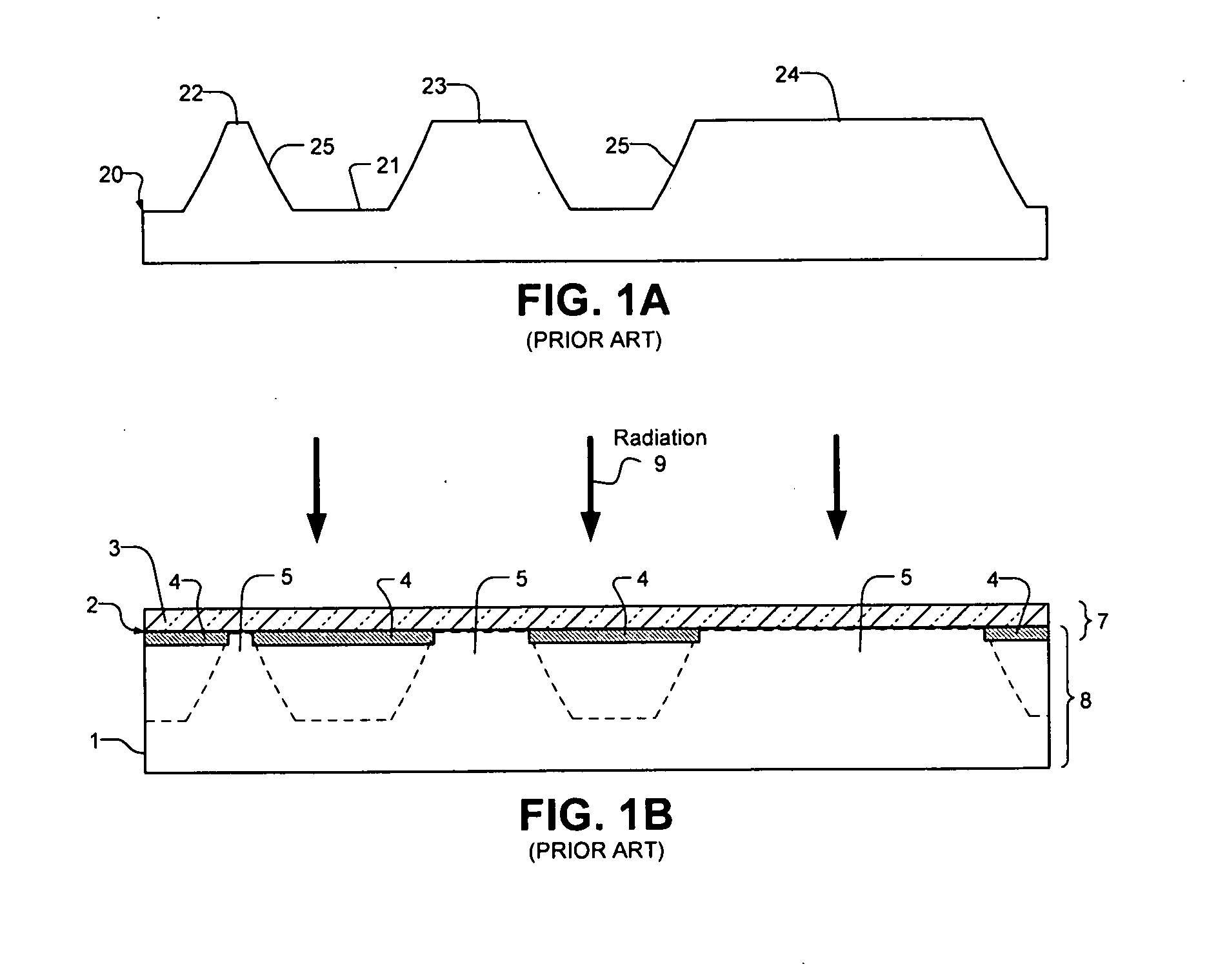
[0032]FIG. 1A is a diagram illustrating an exemplary relief plate 20 according to the prior art. For example, relief plate 20 can be made from photopolymers and used in flexographic printing. Relief plate 20 includes a plate floor 21 which, for example, can be formed from photopolymer material cross-linked by exposure to curing radiation through the back surface. Relief plate 20 also includes relief features 22-24, whose top surfaces are intended to transfer ink to a printing substrate to reproduce image features.

[0033]Small relief feature 22 is amongst the smallest relief feature that can reliably transfer ink to the printing substrate. Some of the smallest small relief features 22 may not have sufficient relief height to reliably accept ink. Alternatively, small relief features 22 that are too small may have sufficient relief height but may not reliably transfer ink to the printing substrate. For example, a small relief feature 22 that is too small may be so narrow that it bends o...


PUM

PropertyMeasurementUnit
diameteraaaaaaaaaa
diameteraaaaaaaaaa
area transparencyaaaaaaaaaa

Abstract

An improved relief printing plate and method for producing said plate is disclosed. Substantially all sizes of relief features resolve a fixed pattern which improves print quality. The pattern is applied to image areas in halftone data used to produce an image mask that is subsequently used to convert a plate precursor into a relief plate. The accuracy, ink density and tonal response of printed images corresponding to relief features that include the pattern are comparable or better than relief features produced without the pattern.

Description

FIELD OF THE INVENTION[0001]The present invention pertains to relief printing and in particular to preparation of an enhanced relief printing plate.BACKGROUND OF THE INVENTION[0002]Flexography, which is one example of relief printing, produces an image on a substrate by transferring ink from the surface of a relief plate, representing the image, directly to a substrate. Relief features in a flexographic plate are typically formed by subjecting a plate precursor to a curing radiation (e.g. ultraviolet light) through an image-wise mask and then developing the precursor to wash away parts of the plate that have not received sufficient curing radiation. The resulting relief features typically comprise solid areas and halftone dots of varying sizes and / or quantities per area to represent a range of tones specified by the image data. For example, a highlight tone can be represented by an array of very small relief dots in an area, a shadow tone can be represented by an array of large dots...

Claims


Application Information

Patent Timeline
Patent Type & Authority Applications(United States)
IPC IPC(8): G03F7/20G03F7/004
CPCB41M1/04G03F7/202G03F5/00B41N1/12G03F7/2016
Inventor STOLT, PETERZWADLO, GREGORY L.ROZZI, WILLIAM A.
Owner MIRACLON CORP
Why Eureka
Try Eureka