
System for on-board metering of recharging energy consumption in vehicles equipped with electrically powered propulsion systems

a technology for propulsion systems and recharging energy, applied in electric devices, transportation and packaging, instruments, etc., can solve the problems of high cost, and inability to make phone calls

Inactive Publication Date: 2010-06-10
LAVA FOUR
View PDF6 Cites 98 Cited by
  • Summary
  • Abstract
  • Description
  • Claims
  • Application Information

AI Technical Summary

Benefits of technology

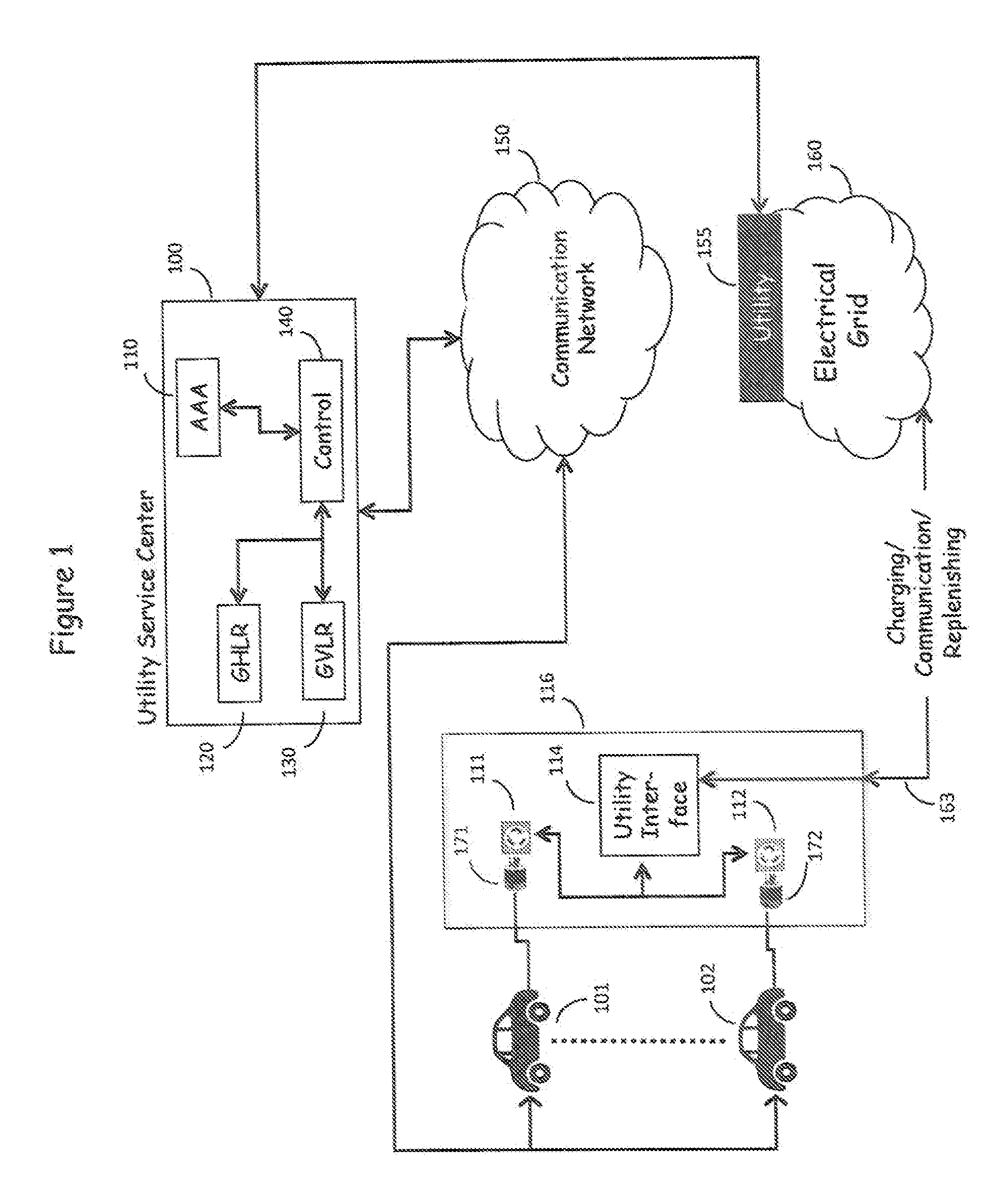
[0020]A second component of the E-Grid is to place the “electric meter” in the vehicle itself to eliminate the need to modify the electric grid. The present Self-Reporting Vehicle provides the vehicle's electric meter with a unique identification of the power source to enable the vehicle to report both the vehicle's energy consumption and the point at which the energy consumption occurred to the utility company via the ubiquitous communications network.
[0021]An advantage of this architecture is that the vehicle is in communication with the utility company, which can implement highly dynamic load management, where any number of vehicles can be “disconnected” and “re-connected” to the electric grid to easily manage peak load problems for geographic areas as small as a city block or as large as an entire city or even a regional area.
[0023]The compelling societal benefit of the novel E-Grid architecture is that it is possible to deploy it today, without a major change in current infrastructure or requiring adding new infrastructure. Virtually every electrical outlet, no matter where located, can be used to charge a vehicle, with the bill for that charge going directly to the given consumer, with the owner of the electrical outlet getting a corresponding credit, and with the payment for electricity going directly to the utility that provided the energy—all in a seamless fashion.

Problems solved by technology

When a cellular subscriber “roamed” out of their home “network”, they couldn't make phone calls, or making phone calls was either extremely cumbersome or expensive or both.

Method used


Image

  • System for on-board metering of recharging energy consumption in vehicles equipped with electrically powered propulsion systems
  • System for on-board metering of recharging energy consumption in vehicles equipped with electrically powered propulsion systems
  • System for on-board metering of recharging energy consumption in vehicles equipped with electrically powered propulsion systems

Examples


utility embodiment

Multi-Utility Embodiment

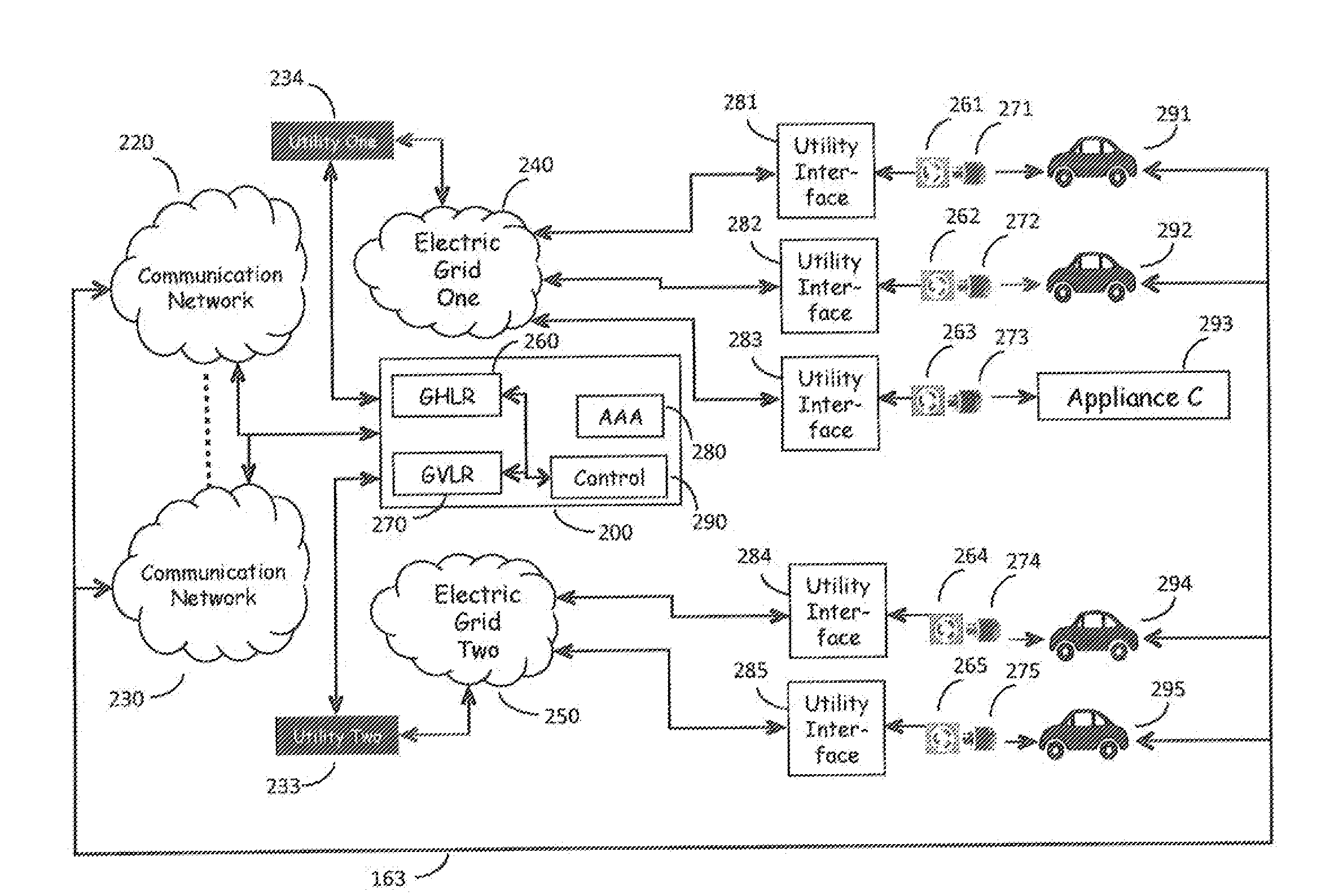
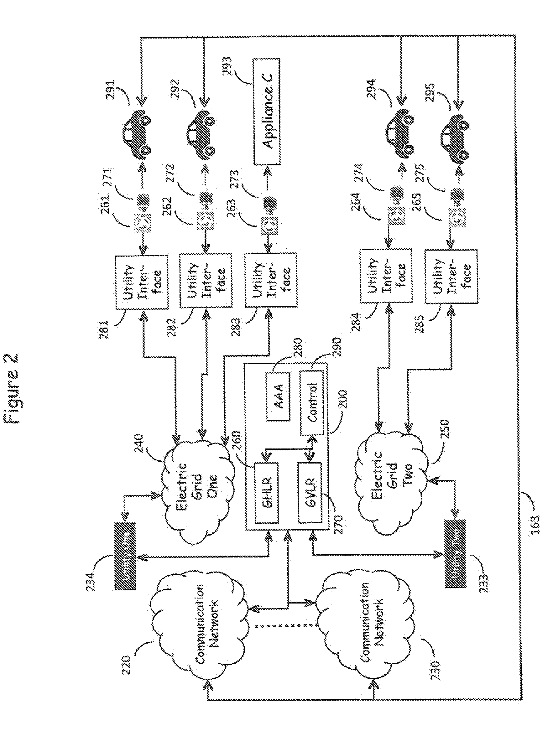
[0037]FIG. 1 is in reality a multidimensional network in which N electric utilities are served by M Electric Grids with corresponding communication networks, as shown in FIG. 2.

[0038]Electric Grids 240, 250 shown in FIG. 2 represent the source of electric power as provided by multiple utility companies which serve a wide geographic area and provide electric power to a multitude of customers via utility interfaces 281-285. The utility interfaces 281-285 serve to measure the energy consumption by the various outlet connected loads, such as Vehicles 291-295. These elements represent the existing, present day electric power delivery infrastructure as described above. Electric power traditionally flows from the electric grid 240, 250 to the utility interfaces 281-285 and thence to the customer's loads—Vehicles 291-295 via plug 261-265-outlet 271-275 combinations—but power also can flow in the reverse direction, from the vehicular battery banks of Vehicles 291-295,...


PUM


Abstract

The System For On-Board Metering Of Recharging Power Consumption In Vehicles Equipped With Electrically Powered Propulsion Systems uses a unique identification of the associated Self-Identifying Outlet and the power consumption as metered on the Self-Reporting Vehicle to enable the Self-Reporting Vehicle to report the Self-Reporting Vehicle's power consumption to the utility company to enable the utility company to bill the vehicle owner and credit the account of the Self-Identifying Outlet for the power consumed by the recharging of the vehicular battery banks.

Description

CROSS-REFERENCE TO RELATED APPLICATIONS[0001]This Application is related to a US Application titled “Self-Identifying Power Source For Use In Recharging Vehicles Equipped With Electrically Powered Propulsion Systems”, and a US Application titled “Network for Authentication, Authorization, and Accounting Of Recharging Processes For Vehicles Equipped With Electrically Powered Propulsion Systems”, both filed on the same date as the present application and incorporating the disclosures of each herein.FIELD OF THE INVENTION[0002]This invention relates to a system for use in recharging vehicles which are equipped with electrically powered propulsion systems, where each outlet provides a unique outlet identification to the vehicle for power consumption billing purposes, where the metering and reporting of power consumption is done by the vehicle.BACKGROUND OF THE INVENTION[0003]It is a problem in the field of recharging systems for vehicles equipped with electrically powered propulsion sys...

Claims


Application Information

Patent Timeline
Patent Type & Authority Applications(United States)
IPC IPC(8): G06F17/00H02J7/04
CPCB60L11/1816Y04S30/14B60L11/1842B60L11/1846B60L11/1848B60L11/185G06Q50/06G07F15/005Y02E60/721Y02T10/7005Y02T90/121Y02T90/128Y02T90/14Y02T90/169Y04S10/126B60L11/1824Y02T10/7072B60L55/00B60L53/65B60L53/665B60L53/11B60L53/18B60L53/34Y02E60/00Y02T10/70Y02T90/12Y02T90/167
Inventor GRAZIANO, JAMES M.KAUSS, GEORGEMCKENNA, DANIEL B.TYLER, RICHARD M.
Owner LAVA FOUR
Learn More