Method and structure for hybrid thermal solar module

a solar module and hybrid technology, applied in the field of solar devices, can solve the problems of increasing the rate of warming, increasing the sea level, and reducing the efficiency of solar energy generation

Inactive Publication Date: 2010-06-17
SUNEDISON INC
View PDF5 Cites 30 Cited by
  • Summary
  • Abstract
  • Description
  • Claims
  • Application Information

AI Technical Summary

Benefits of technology

[0009]According to the present invention, techniques related to solar devices are provided. More particularly, the present invention provides a method and system including a combined thin film photovoltaic and thermal solar system, which takes advantage of a single form factor, according to a specific embodiment. Alternatively, the present method and system can be applied to other types of photovoltaic materials, such as crystalline silicon, polysilicon, organic photovoltaic materials, and others. Merely, by way of example, the present invention has been applied to a thermal solar module configured on a building structure, but it would be recognized that the invention has a much broader range of applications.

Problems solved by technology

Obviously, our daily lives depend, for the most part, upon oil or other fossil fuels, which are being depleted and becoming increasingly scarce.
The increase in temperature is expected to cause extreme weather conditions and a drastic size reduction of the polar ice caps, which in turn will lead to higher sea levels and an increase in the rate of warming.
Ultimately, other effects include mass species extinctions, and possibly other uncertainties that may be detrimental to human beings.
Although solar panels have been used successful for certain applications, there are still certain limitations.
Solar cells are often costly.
Depending upon the geographic region, there are often financial subsidies from governmental entities for purchasing solar panels, which often cannot compete with the direct purchase of electricity from public power companies.
Such wafer materials are often costly and difficult to manufacture efficiently on a large scale.
Availability of solar panels is also somewhat scarce.
That is, solar panels are often difficult to find and purchase from limited sources of photovoltaic silicon bearing materials.

Method used


Image

  • Method and structure for hybrid thermal solar module
  • Method and structure for hybrid thermal solar module
  • Method and structure for hybrid thermal solar module

Examples


Embodiment Construction

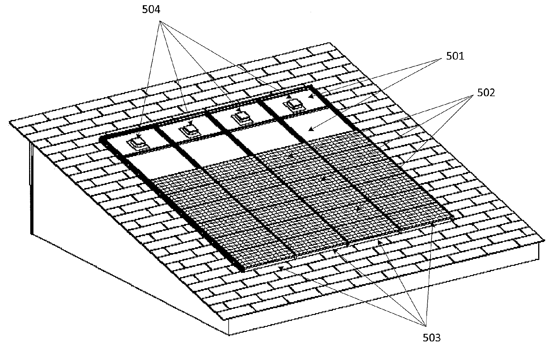
[0021]According to the present invention, techniques related to solar devices are provided. More particularly, the present invention provides a method and system including a combined thin film photovoltaic and thermal solar system, which takes advantage of a single form factor, according to a specific embodiment. Alternatively, the present method and system can be applied to other types of photovoltaic materials, such as crystalline silicon, polysilicon, organic photovoltaic materials, and others. Merely, by way of example, the present invention has been applied to a thermal solar module configured on a building structure, but it would be recognized that the invention has a much broader range of applications.

Hybrid PV / Thermal Flat-Plate Collector

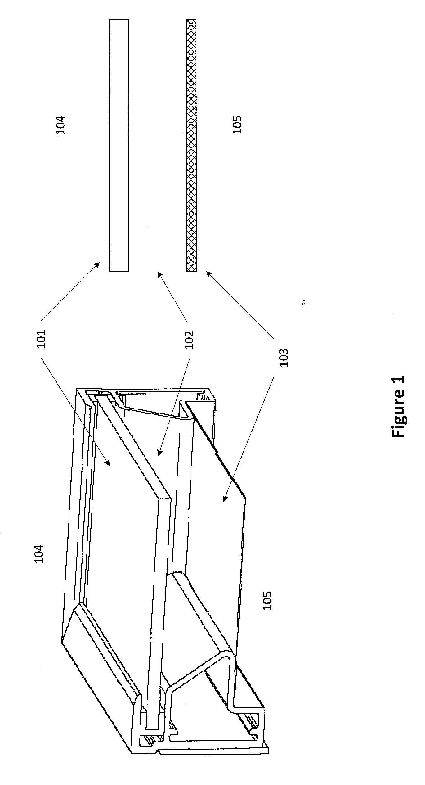
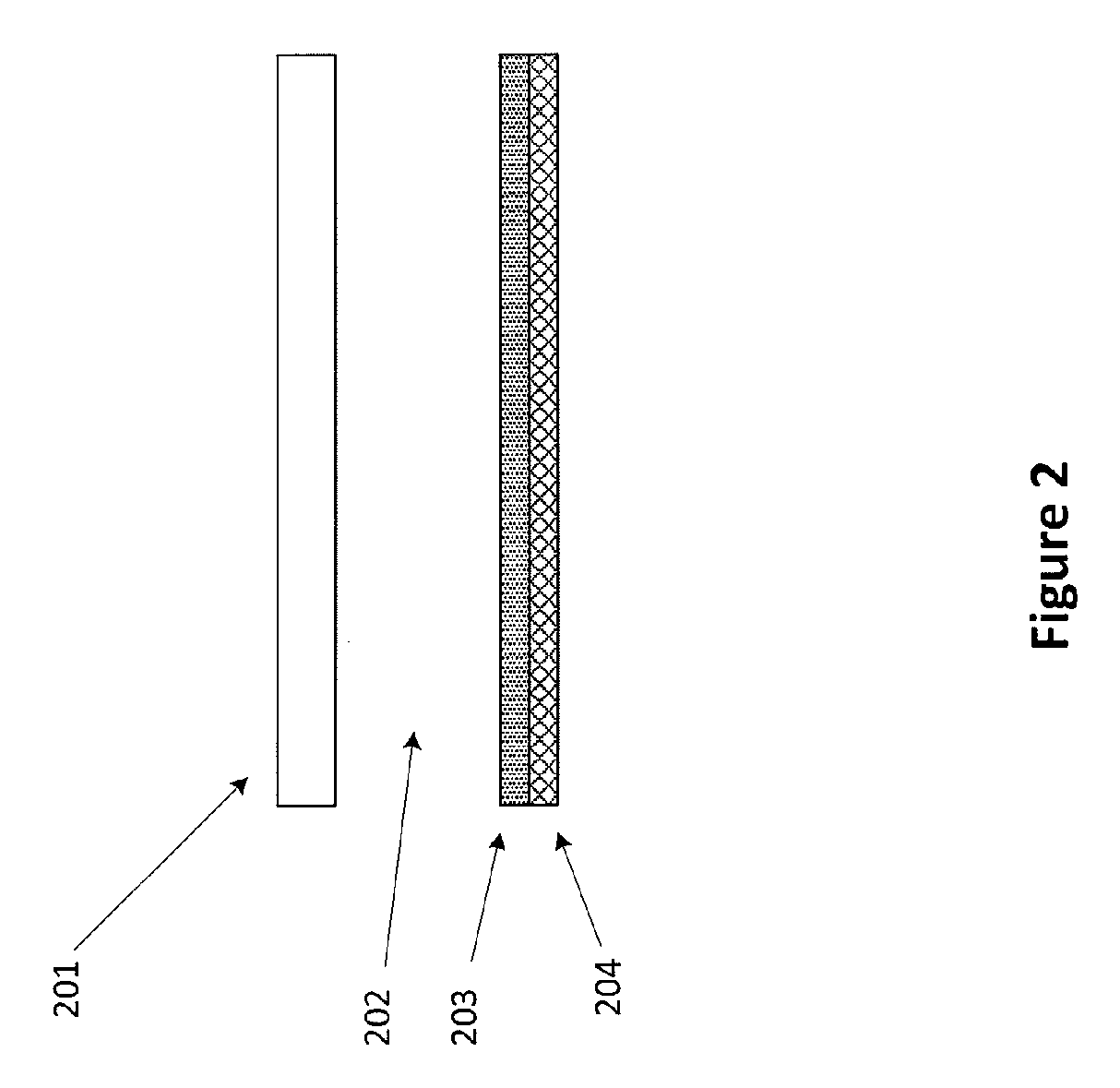
[0022]In a specific embodiment of solar thermal collectors, a glazing is used to improve the performance of the collector. As used herein, the term “thermal collectors” can be devices that convert the sun's energy into heat, although there c...


PUM


Abstract

A solar module assembly and method. The assembly comprises a substantially transparent or semi-transparent surface provided on a first substrate member. The assembly includes an absorber material overlying a second substrate member. A spacing is provided between the semi-transparent surface of the first substrate and the second substrate, which has a first side and a second side. In a specific embodiment, the assembly has a fluid transport region disposed within a vicinity of either the first side or the second side of the second substrate. In a preferred embodiment, the assembly has a photovoltaic device configured from at least the absorber material to generate electrical energy and a thermal energy device configured from at least the absorber material to generate thermal energy using the a fluid provided in the fluid transport region.

Description

CROSS-REFERENCES TO RELATED APPLICATIONS[0001]This application claims priority to U.S. Provisional Application No. 61 / 122,732, filed Dec. 16, 2008, commonly assigned, and incorporated by reference herein for all purpose.BACKGROUND OF THE INVENTION[0002]The present invention relates to techniques for solar devices. More particularly, the present invention provides a method and system including a combined thin film photovoltaic and thermal solar system, which takes advantage of a single form factor, according to a specific embodiment. Merely, by way of example, the present invention has been applied to a thermal solar module configured on a building structure, but it would be recognized that the invention has a much broader range of applications.[0003]Over the past centuries, the world population of human beings has exploded. Along with the population, demand for resources has also grown explosively. Such resources include raw materials such as wood, iron, and copper and energy, such ...

Claims


Application Information

Patent Timeline
Patent Type & Authority Applications(United States)
IPC IPC(8): H01L31/042H01L35/00
CPCH01L35/30Y02E10/50Y02E10/60H02S10/10H02S20/00H02S40/44H01L31/048H01L31/03767H02S20/23Y02E10/40F24S80/52F24S25/20F24S70/10F24S80/58F24S80/56Y02B10/10H10N10/13
Inventor DYREBY, JOHN JAMESPLAISTED, JOSHUA REED
Owner SUNEDISON INC
Why Eureka
Try Eureka