
Mechatronic suspension system and method for shock absorbing thereof

a technology of mechatronic suspension and shock absorption, which is applied in the direction of hoisting equipment, gearing, transportation and packaging, etc., can solve the problems of large volume of mechanical devices, inability to meet industrial requirements, and inability to meet the performance of the above-mentioned suspension system. achieve the effect of improving the performance of vehicle systems and expanding the scope of application

Inactive Publication Date: 2010-06-17
NAT TAIWAN UNIV
View PDF1 Cites 30 Cited by
  • Summary
  • Abstract
  • Description
  • Claims
  • Application Information

AI Technical Summary

Benefits of technology

[0008]The purpose of the invention is to provide a mechatronic suspension system and a method for shock absorbing thereof, in order to improve the technique of existing suspension systems, and raise the shock absorbing effects.
[0016]The mechatronic suspension system proposed by the invention can improve the performance of vehicle systems of low-stiffness, such as sedans, such that its scope of application is more extensive.

Problems solved by technology

When the vehicle is driven on the road, it suffers from various shock and impact from ground and driving conditions, wherein part of shock and impact can be absorbed by the tires, and most of shock and impact must be absorbed by the suspension system installed between the tires and car body.
However, the performance of the above-mentioned suspension systems is not satisfied for the industrial requirement.
However, the network synthesis for high-order impedance can be very complicated and the volume of mechanical devices is too large to install in the vehicle chassis actually.

Method used


Image

  • Mechatronic suspension system and method for shock absorbing thereof
  • Mechatronic suspension system and method for shock absorbing thereof
  • Mechatronic suspension system and method for shock absorbing thereof

Examples


Embodiment Construction

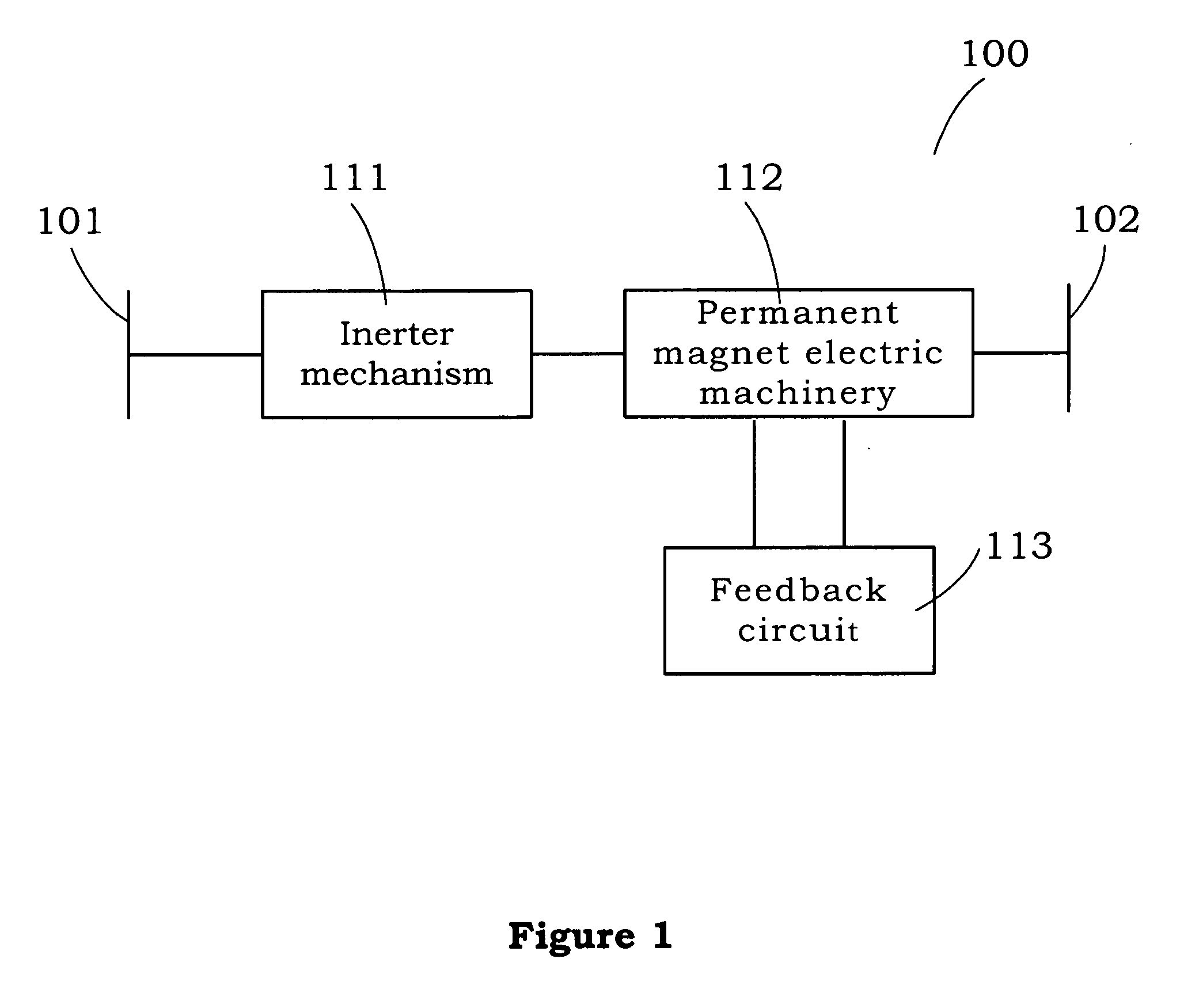
[0023]FIG. 1 illustrates the block diagram of the whole mechatronic suspension system apparatus of the invention. The mechatronic suspension system 100 composes of an inerter mechanism 111, a permanent magnet electric machinery 112, and a feedback circuit 113. The mechatronic suspension system 100 is connected to two terminals, which are the first terminal 101 and the second terminal 102. The mechatronic suspension system 100 can be applied to various fields, such as the vehicle and motorcycle industry, train industry, building industry, shock absorbing systems, precision machinery, and optical shock absorbing desks etc.

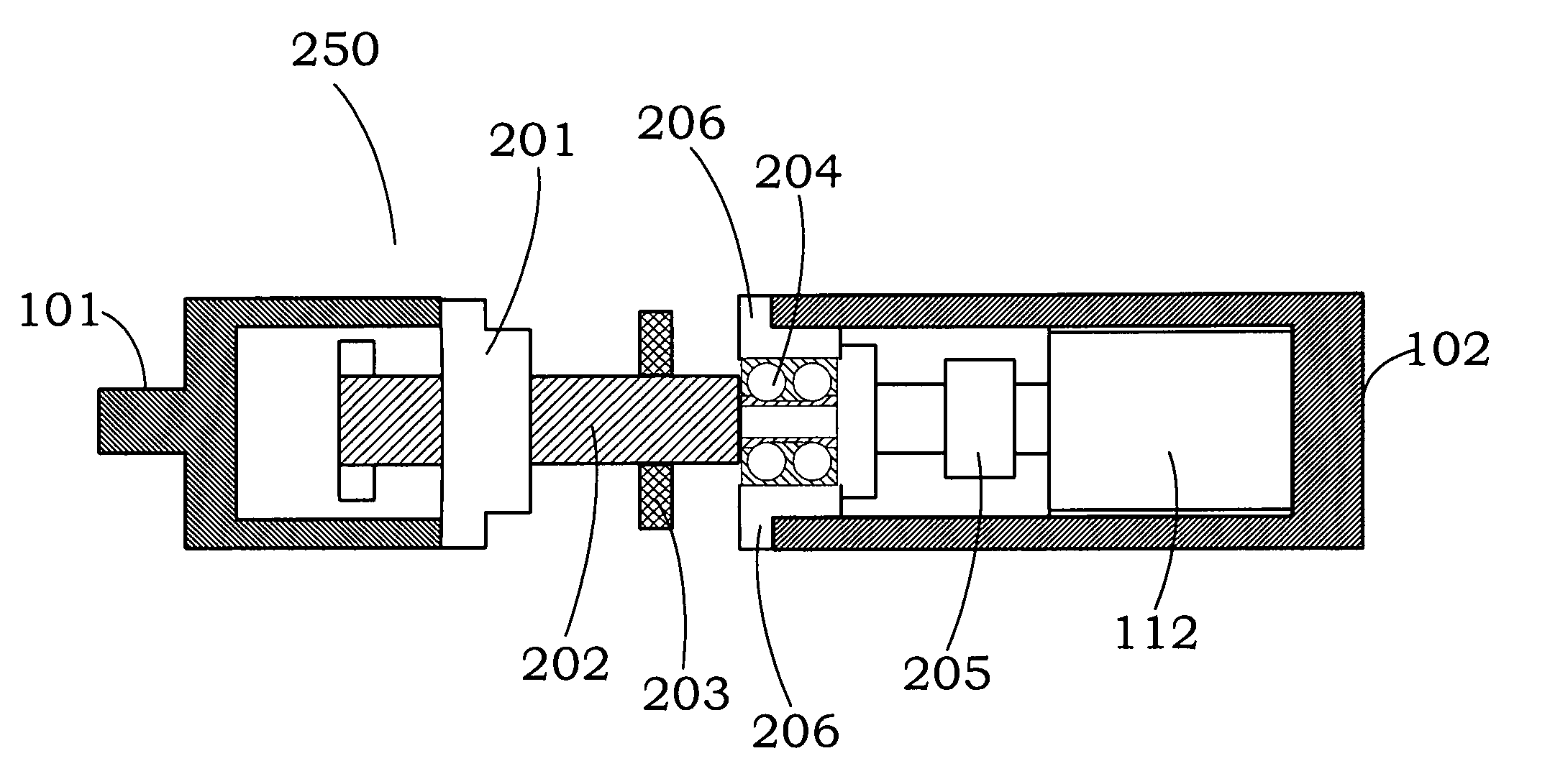
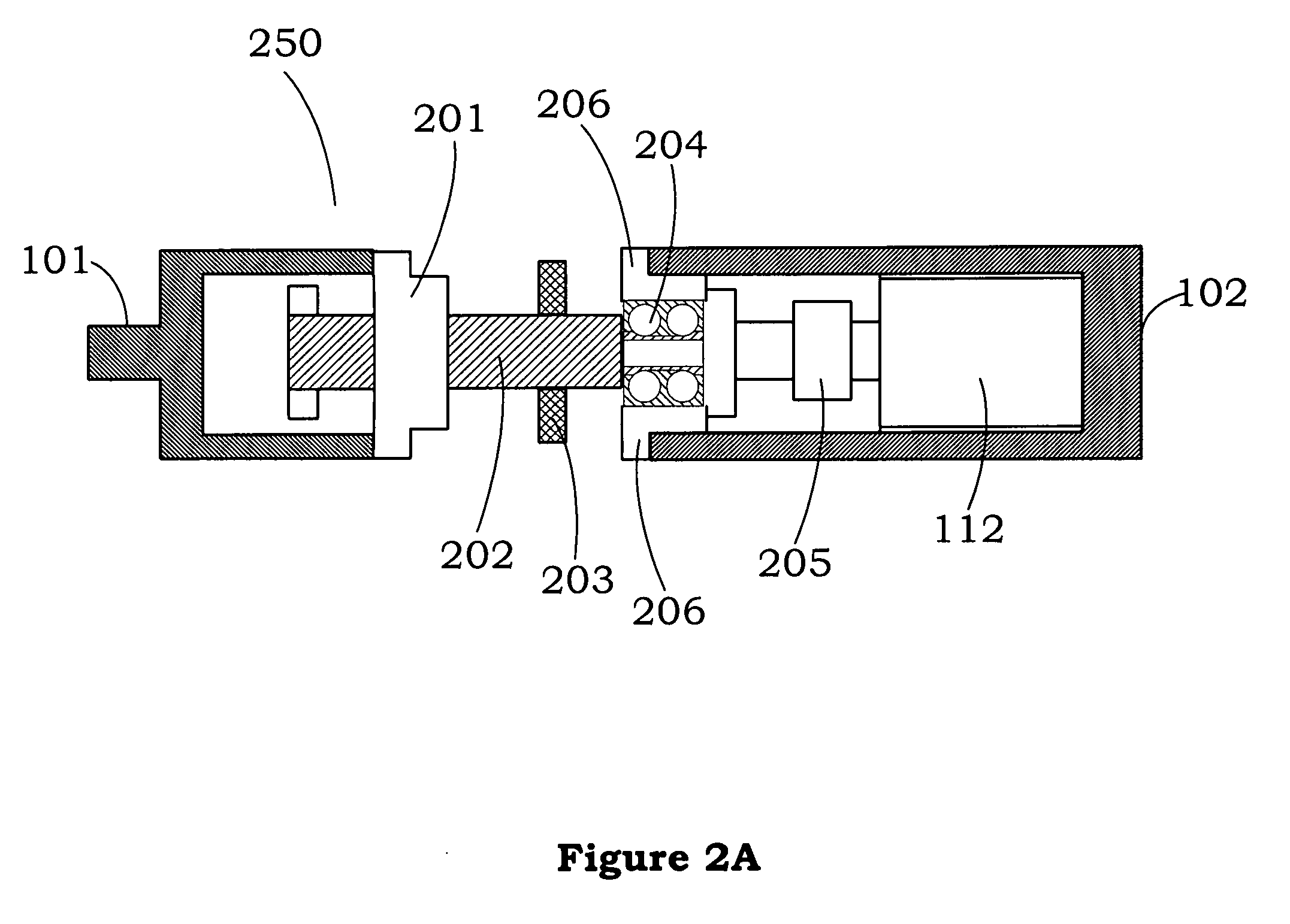
[0024]As shown in FIG. 2A, the inerter mechanism (ball-screw inerter) 250 also composes of the nut 201, screw 202, flywheel 203, bearing 204, coupling 205, and bearing socket 206. The nut 201 is fixed on the first terminal 101 with screw 202. The screw 202 is coupled with flywheel 203 and bearing 204. The bearing socket 206 is used to fix the bearing 204. The couplin...


PUM


Abstract

The invention provides a mechatronic suspension system and a method for shock absorbing thereof. The invention applies the analogies between mechanical and electronic networks to propose a mechatronic suspension system, which combines a ball-screw inerter and a permanent magnet electric machinery, such that the complicated network structure can be realized through the combination of mechanical and electronic networks. The mechatronic suspension system is connected to two terminals, and consists of the inerter mechanism, the permanent magnet electric machinery and the feedback circuit. The inerter mechanism is connected to the terminals to transfer the linear motion into the rotational motion. The permanent magnet electric machinery is connected to the inerter mechanism to generate a corresponding voltage. And the feedback circuit is connected to the permanent magnet electric machinery to provide suitable system impedance and to generate a feedback force.

Description

BACKGROUND OF THE INVENTION[0001]1. Field of the Invention[0002]The invention relates to a suspension system and a method for shock absorbing thereof, more particularly to a mechatronic suspension system and a method for shock absorbing thereof.[0003]2. Description of the Prior Art[0004]When the vehicle is driven on the road, it suffers from various shock and impact from ground and driving conditions, wherein part of shock and impact can be absorbed by the tires, and most of shock and impact must be absorbed by the suspension system installed between the tires and car body. It can prevent the parts of car body from damage, and make the passengers feel comfortable. Thus the suspension system not only can absorb the outside shock and impact, but also can have direct and positive influence on the stability and manipulation of driven vehicle.[0005]As for the major design and application of the vehicle suspension system at present, the mechanical devices such as the spring device, air cu...

Claims


Application Information

Patent Timeline
IPC IPC(8): B60G17/00F16H1/24F16F15/03
CPCB60G13/14B60G17/015B60G2202/16B60G2202/25Y10T74/19749B60G2204/419F16F15/03F16F2232/06B60G2202/42
Inventor WANG, FU-CHENGCHAN, HSIANG-AN
Owner NAT TAIWAN UNIV
Learn More