All-conditions tunnel boring machine

a tunnel boring machine, all-condition technology, applied in shaft equipment, shaft lining, slitting machines, etc., can solve the problems of inconvenient testing of inability to completely test the geology of the path, and chips that cannot be broken from the tunnel fa

Inactive Publication Date: 2010-06-17
THE ROBBINS CO
View PDF17 Cites 38 Cited by
  • Summary
  • Abstract
  • Description
  • Claims
  • Application Information

AI Technical Summary

Benefits of technology

[0008]The following presents a simplified summary of the invention in order to provide a basic understanding of some example aspects of the invention. This summary is not an extensive overview of the invention. Moreover, this summary is not intended to

Problems solved by technology

In some environments, it is cost prohibitive to completely test the geology of the path that the tunnel will traverse.
The transfer of this high thrust through the rolling disc cutters create fractures in the rock causing chips to break away from the tunnel face.
Open machines can get inundated with debris if the condition of the terrain that is being bored becomes unstable due to a lack of shields located behind the cutter h

Method used


Image

  • All-conditions tunnel boring machine
  • All-conditions tunnel boring machine
  • All-conditions tunnel boring machine

Examples


Embodiment Construction

[0037]Example embodiments that incorporate one or more aspects of the present invention are described and illustrated in the drawings. These illustrated examples are not intended to be a limitation on the present invention. For example, one or more aspects of the present invention can be utilized in other embodiments and even other types of devices. Moreover, certain terminology is used herein for convenience only and is not to be taken as a limitation on the present invention. Still further, in the drawings, the same reference numerals are employed for designating the same elements.

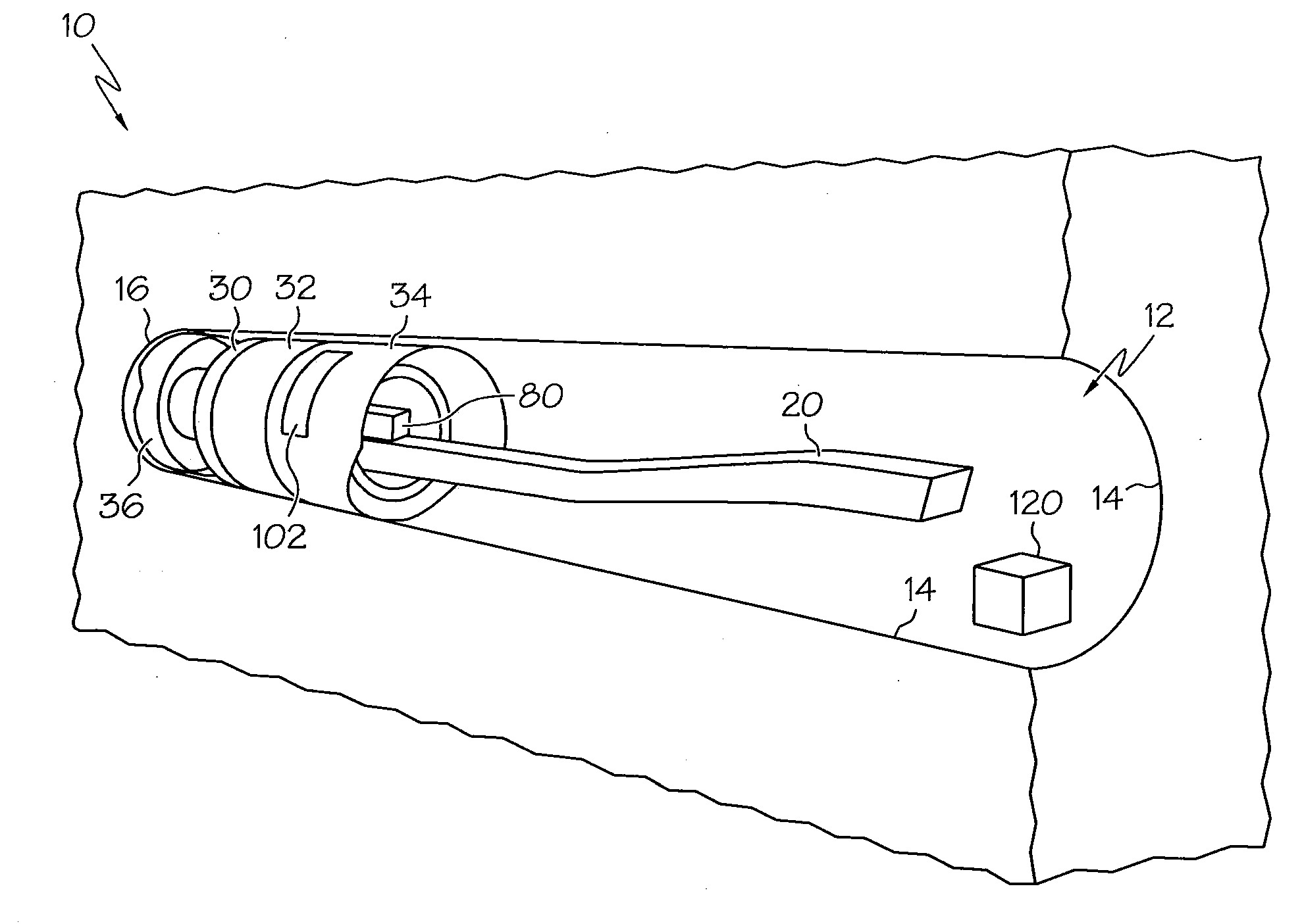
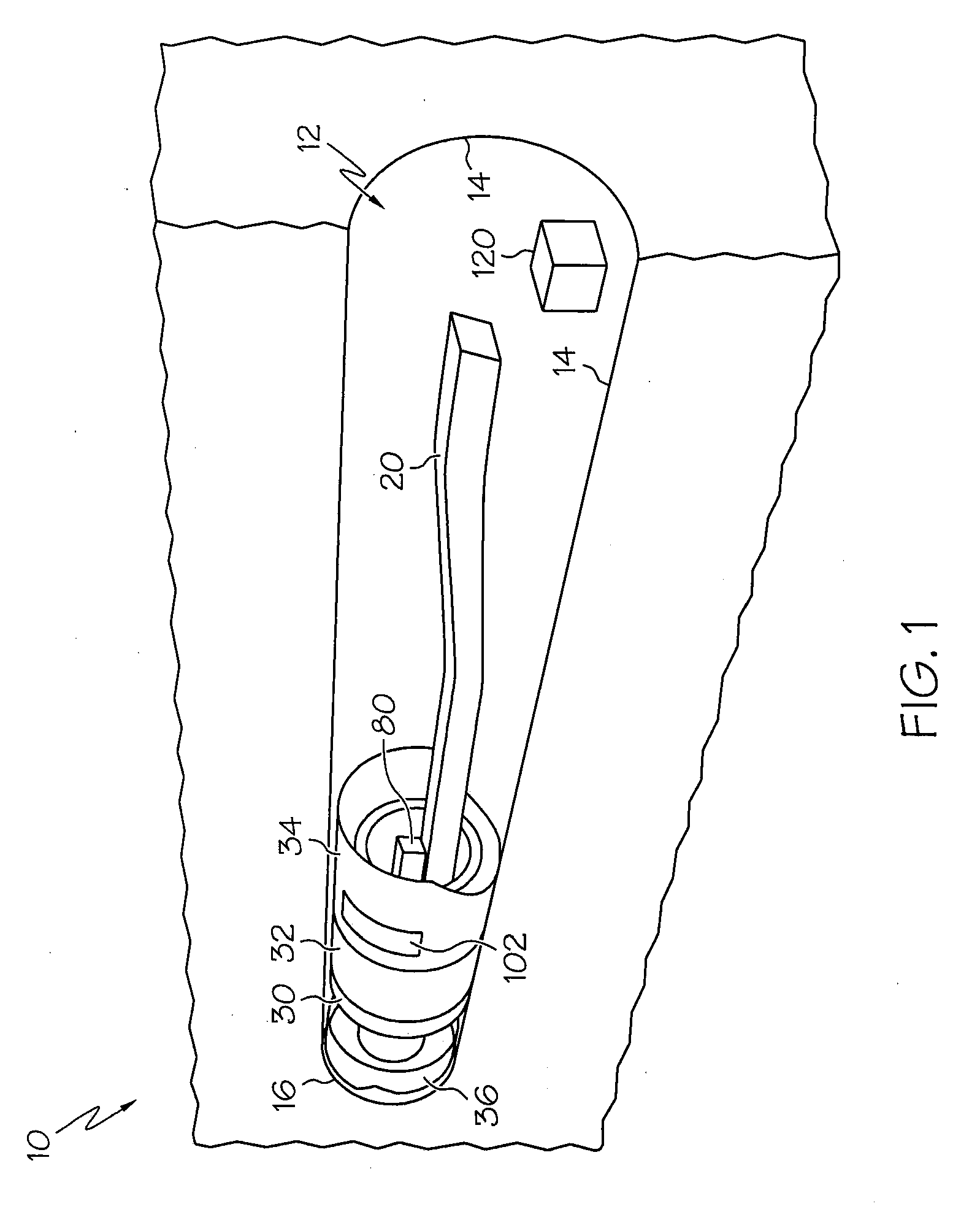
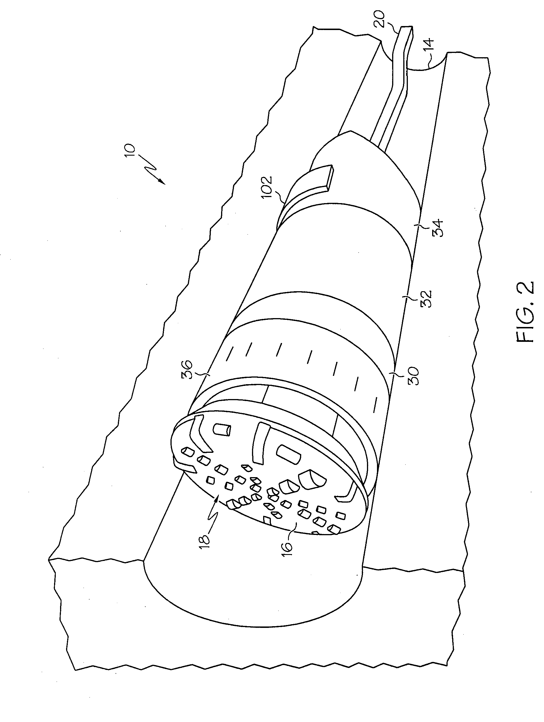
[0038]As shown in FIG. 1, an example All-Conditions Tunneler (ACT) tunnel boring machine (TBM) 10 is provided. The TBM 10 is configured to bore out a tunnel 12 from the earth through different geological conditions, such as rock or through a mountain. Difficult geological conditions can include one or several of the following conditions:

[0039]Squeezing ground; convergence within minutes / hours of opening;...


PUM


Abstract

A tunnel boring machine is provided comprising a cutter head, a main beam, a first, second, and third shield; and a ground conditioning work zone within the first shield, a gripper assembly, a segment erector arm for lining the tunnel, and at least one propulsion mechanism. The ground conditioning work zone includes at least one probing device for probing the terrain ahead of the cutter head. The first shield is configured to be retracted relative to the second shield to provide access for the ground conditioning work zone to apply at least one ground support device. The at least one propulsion mechanism moves the cutter head, the first and the second shield forward while the third shield and the gripper assembly remain stationary. The ground support devices can include filling a hole with a ground conditioning agent; and placing a bolt, ring beam, mesh, or shotcrete in/on the tunnel wall.

Description

BACKGROUND OF THE INVENTION[0001]The present invention relates generally to a tunnel boring machine (TBM) and other machines that are configured to drill tunnels through various ground conditions and a wide range of geology. In some environments, it is cost prohibitive to completely test the geology of the path that the tunnel will traverse.[0002]A main beam TBM is considered an “open” machine. The main beam TBM can have a shield in a forward location but does not include shields in the rearward locations of the TBM. The main beam TBM includes a cutter head and hydraulic propel cylinders that push the cutters into the rock. The transfer of this high thrust through the rolling disc cutters create fractures in the rock causing chips to break away from the tunnel face. Gripper shoes can be provided to push on the sidewalls to react the machine's forward thrust. The gripper shoes can move along the main beam. At the end of a stroke, the rear legs of the machine are lowered, the grippers...

Claims


Application Information

Patent Timeline
IPC IPC(8): E21C29/00
CPCE21D9/001E21D20/003E21D9/082E21D9/0873
Inventor HOME, LOKKHALIGHI, BRIANTURNER, JOHN
Owner THE ROBBINS CO
Why Eureka
Try Eureka