Mismatched Filter

Inactive Publication Date: 2010-06-17
FAM ADLY T
View PDF7 Cites 12 Cited by
  • Summary
  • Abstract
  • Description
  • Claims
  • Application Information

AI Technical Summary

Benefits of technology

[0005]The present solution provides methods and systems for realizing hardware efficient mismatched filters for pulse compression codes. For pulse compression codes with sufficiently small sidelobe structures, such as in th

Problems solved by technology

Since all their coefficients are optimized, len

Method used


Image

  • Mismatched Filter
  • Mismatched Filter
  • Mismatched Filter

Examples


Example

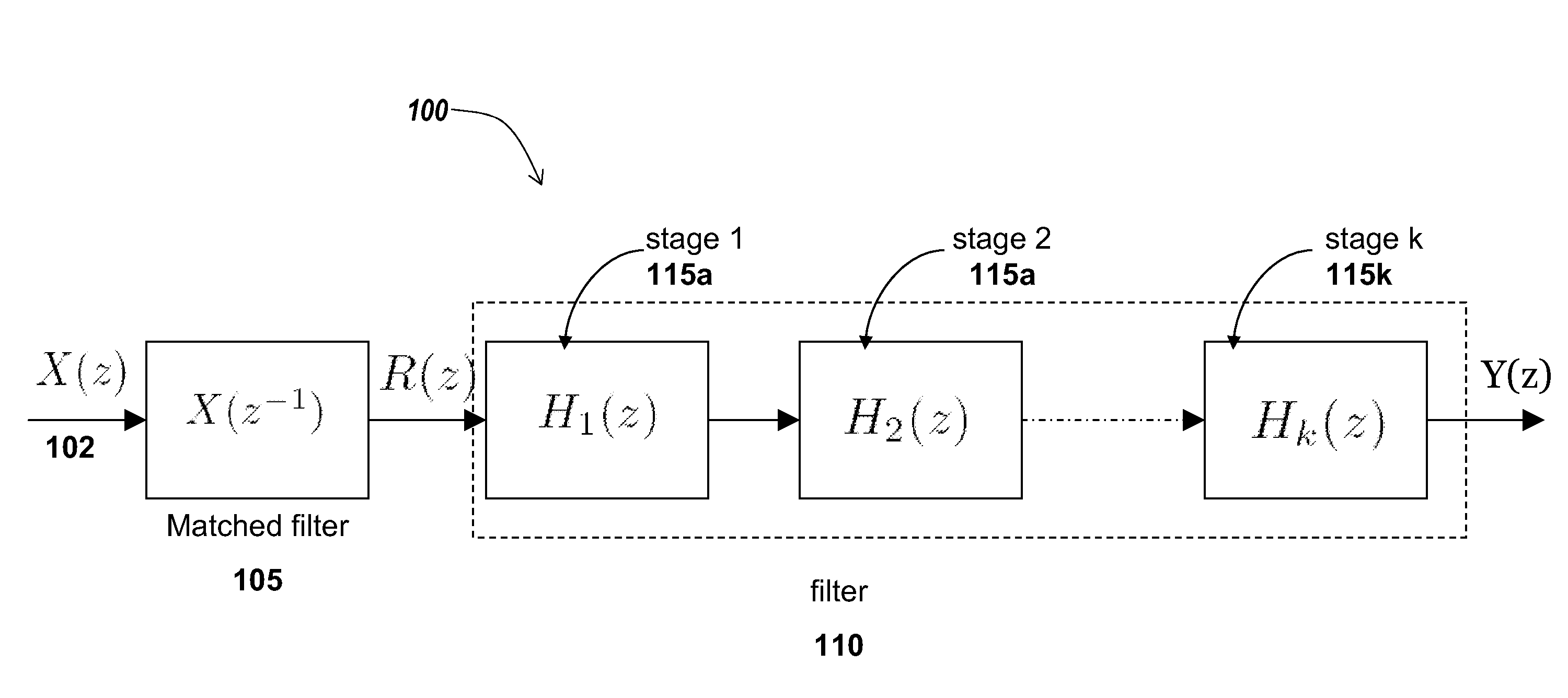
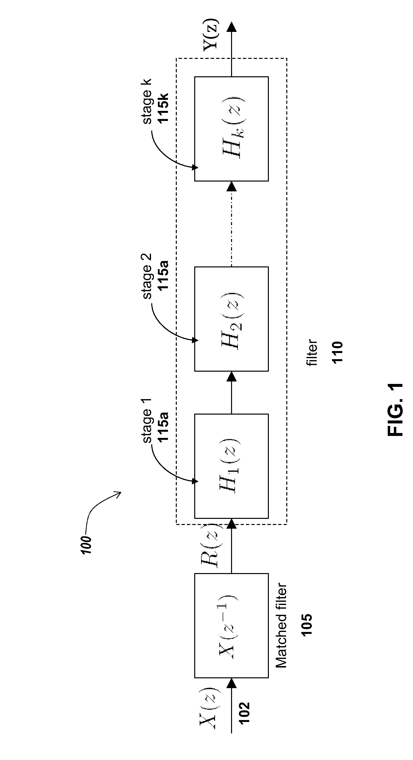
[0032]Referring to FIG. 1, a block diagram of an embodiment of a system including a multistage mismatched filter in cascade with a matched filter is shown and described. In brief overview, the system 100 includes a matched filter 105. The system further includes a filter 110 In some embodiments, the filter 110 includes one or more filter stages 115a-115n (in general 115).

[0033]The system 100 may be implemented and operated on any type and form of electronic or computing device 101 (not shown). In one embodiment, the device 101 may be a computing device such as a desktop computer or a laptop computer. In another embodiment, the device 101 may be a microcomputer. In still another embodiment the device 101 may be a microcontroller. In yet another embodiment, the device 101 may be a digital signal processor (DSP) such as manufactured by Texas Instruments of Dallas, Tex. The device 101 and the system 100 may also be implemented on a software platform such as MATLAB or SIMULINK manufactur...


PUM


Abstract

The present solution provides methods and systems for realizing hardware efficient mismatched filters for pulse compression codes. For pulse compression codes with sufficiently small sidelobe structures, such as in the cases of odd length Barker codes, the proposed filters require a small number of adders and multipliers per output. This translates to significantly reduced chip-area and lower power consumption when implemented on a chip.
In one aspect, the present application features a method for suppressing an undesired part of a waveform. The method includes filtering a signal via a filter. In one embodiment, the signal includes an expected waveform that can be represented as a sum of the desired part and the undesired part. The impulse response of the filter can be represented a sum of the desired part and a negative of the undesired part.

Description

RELATED APPLICATION[0001]This application incorporates by reference in its entirety: “Multiplicative Mismatched Filters for Optimum Range Sidelobe Suppression in Barker Code Reception,” U.S. application Ser. No. 11 / 559,776, filed Nov. 14, 2006.FIELD OF THE INVENTION[0002]The present application is generally directed to methods and systems for sidelobe suppression in pulse compression codes.BACKGROUND[0003]Pulse compression codes are designed such that the transmitted energy is uniformly spread in time while the autocorrelation function (ACF) has most of its energy in the mainlobe. Upon matched filtering of such codes, the output is their ACF. The peak sidelobe level (PSL) in the ACF of any good code is required to be as low as possible. Barker codes have the least PSL (of unity magnitude) among all biphase codes. In most applications, it is desirable to reduce the sidelobes further. This is achieved via mismatched filters.[0004]Mismatched filters for sidelobe suppression can be base...

Claims


Application Information

Patent Timeline
IPC IPC(8): G01S7/28
CPCG01S7/285G01S13/288H03H17/0286H03H17/0254H03H17/0223
Inventor FAM, ADLY T.SARKAR, INDRANIL
Owner FAM ADLY T
Why Eureka
Try Eureka