Pump having pulsation-reducing engagement surface

a technology of engagement surface and plunger, which is applied in the field of plungers, can solve the problems of inability to apply to other situations, inability to tilt the wave cam to vary the displacement of the plunger, and limited application of fixed displacement pumps, so as to reduce the pulsation

Inactive Publication Date: 2010-06-17
CATERPILLAR INC
View PDF39 Cites 26 Cited by
  • Summary
  • Abstract
  • Description
  • Claims
  • Application Information

AI Technical Summary

Benefits of technology

[0011]In yet another aspect, the present disclosure is directed to a method of pressurizing fluid. The method may include reciprocating a plurality of plungers to produce a flow of pressurized fluid, and adjusting a displacement of the plungers to vary a rate of fluid pressurizing. The method may also include inducing undulations in movement of the plungers during reciprocation to reduce a pulsation in the flow of pressurized fluid.

Problems solved by technology

While the pump of the '949 patent may be suitable for refrigerant purposes, it may lack applicability to other situations.
Specifically, because the wave cam is fixed to the drive shaft, tilting of the wave cam to vary displacement of the plungers may not be possible.
And, fixed displacement pumps may find limited application in, for example, machine hydraulic, lubrication, coolant, or fuel system arrangements.
Further, the wave cam may induce undesired flow pulsations within the refrigerant flow.
Lastly, the wave cam of the '949 patent may provide little benefit to a rotary plunger type pump

Method used


Image

  • Pump having pulsation-reducing engagement surface
  • Pump having pulsation-reducing engagement surface
  • Pump having pulsation-reducing engagement surface

Examples


Embodiment Construction

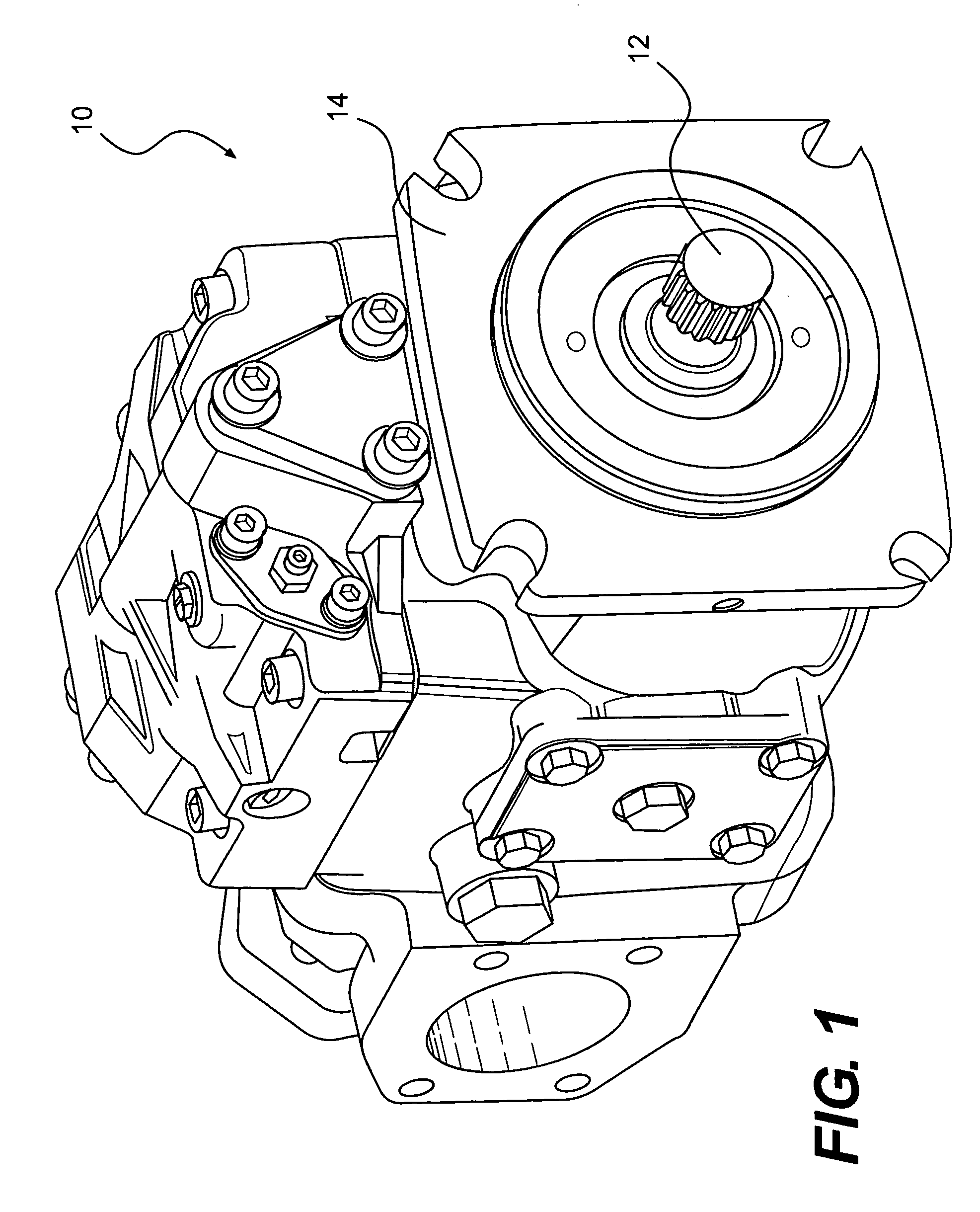
[0018]FIG. 1 illustrates a pump 10. In one embodiment, pump 10 may be driven by an external source of power (not shown), such as a combustion engine, via a driveshaft 12. As such, driveshaft 12 may extend from one end of a pump housing 14 for engagement with the engine.

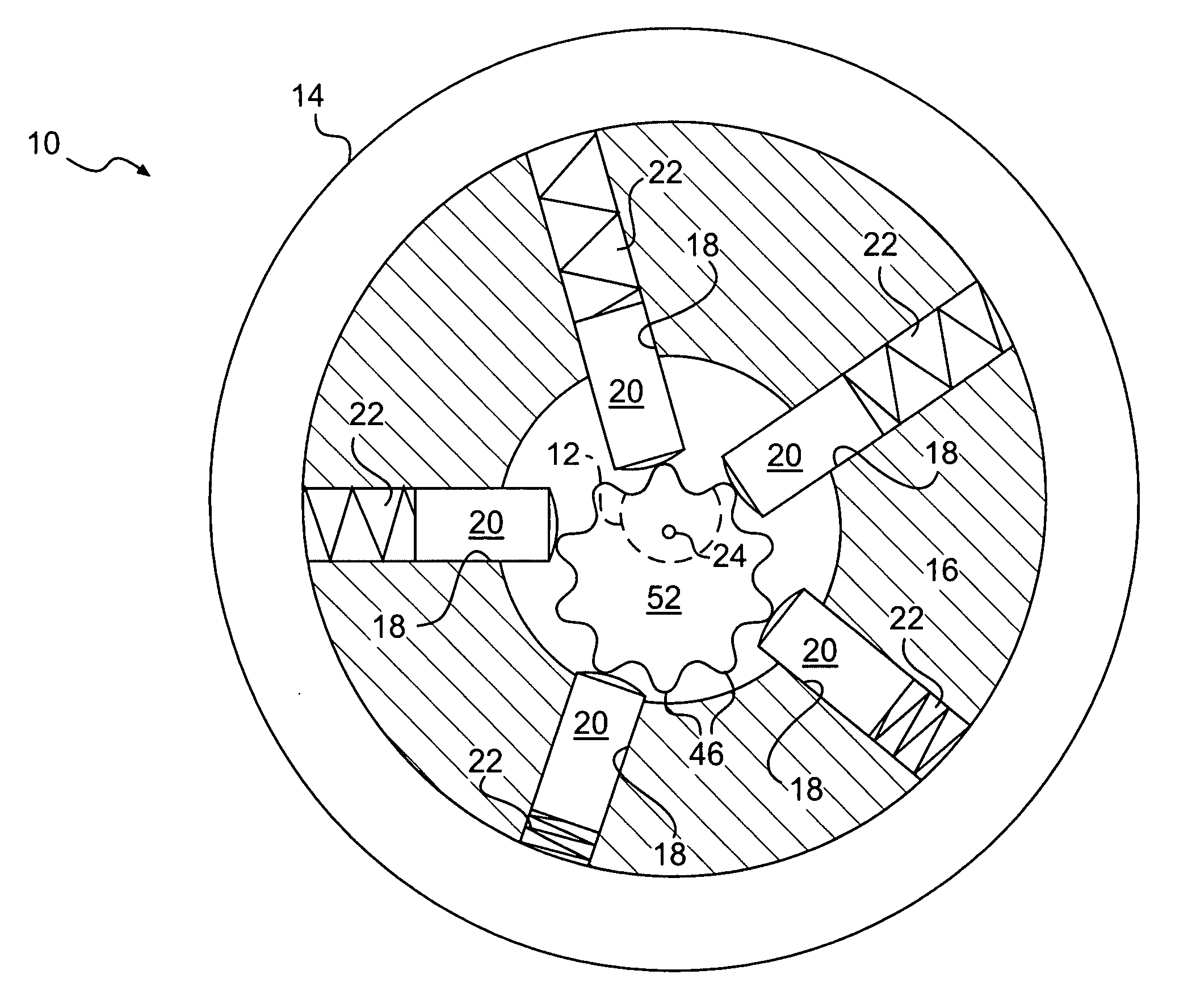
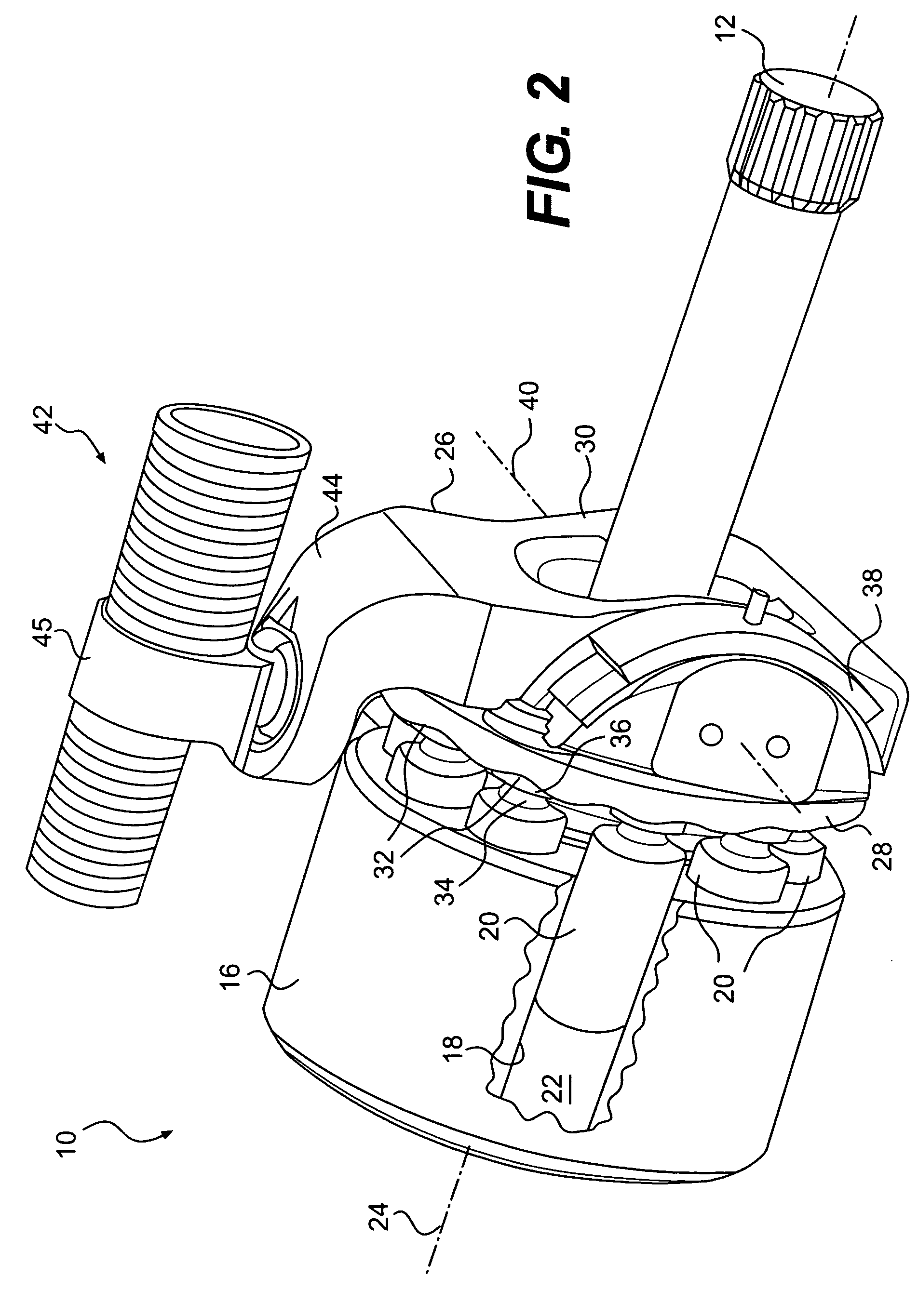
[0019]As illustrated in FIG. 2, housing 14 may enclose a body 16 at least partially defining a plurality of barrels 18 (only one shown). Pump 10 may also include a plurality of plungers 20, one plunger 20 slidingly disposed within each barrel 18. Each barrel 18 and each associated plunger 20 may, together, at least partially define a pumping chamber 22. It is contemplated that any number of pumping chambers 22 may be included within body 16 and symmetrically and radially disposed about a central axis 24. In the embodiment of FIG. 2, seven pumping chambers 22 are included within body 16. Although central axis 24 is shown in FIG. 2 as being coaxial with driveshaft 12, it is contemplated that central axis 24 may be at an...


PUM


Abstract

A pump is disclosed. The pump may have a housing, and a body disposed within the housing and at least partially defining a plurality of barrels. The pump may also have a plurality of plungers associated with the plurality of barrels, and a plunger engagement surface. The plunger engagement surface may have geometry configured to reciprocate the plurality of plungers within the plurality of barrels as the plurality of plungers rotate relative to the plunger engagement surface, and a plurality of undulations configured to reduce a flow pulsation of the pump.

Description

TECHNICAL FIELD[0001]The present disclosure relates generally to a pump and, more particularly, to a pump having a pulsation-reducing engagement surface.BACKGROUND[0002]Hydraulic tool systems typically employ multiple actuators provided with high-pressure fluid from a common pump. In order to efficiently accommodate the different flow and / or pressure requirements of the individual actuators, these systems generally include a pump having variable displacement. Based on individual and / or combined flow and pressure requirements, the pump changes a fluid displacement amount to meet demands. When demand is low, the displacement is reduced to conserve energy.[0003]Typical variable displacement pumps used in hydraulic tool systems are known as axial plunger or swashplate-type pumps. This type of pump includes a plurality of plungers held against a plunger engagement surface of a tiltable swashplate. In most situations, the swashplate is generally planar and includes a smooth surface. A joi...

Claims


Application Information

Patent Timeline
Patent Type & Authority Applications(United States)
IPC IPC(8): F04B1/04
CPCF04B9/042F04B53/001F04B11/00F04B9/045
Inventor MEHTA, VIRAL S.NELSON, BRYAN E.
Owner CATERPILLAR INC
Why Eureka
Try Eureka