Source gas generating device and film forming apparatus

a gas generating device and gas technology, applied in the direction of vacuum evaporation coating, chemical vapor deposition coating, coating, etc., can solve the problems of liquid source likely to decrease, decrease of film forming rate, and source degradation or deterioration, so as to suppress the thermal degradation of the source and suppress the degradation or deterioration. , the effect of high quality

Inactive Publication Date: 2010-06-24
TOKYO ELECTRON LTD
View PDF2 Cites 19 Cited by
  • Summary
  • Abstract
  • Description
  • Claims
  • Application Information

AI Technical Summary

Benefits of technology

[0015]In accordance with the present disclosure, when the film forming source gas is produced by liquefying the solid source and vaporizing the liquid source, the liquid accommodation unit for accommodating the liquid source obtained by liquefying the solid source is divided, via the liquid flowing region, into the region (first region) to be supplied with the solid source and the region (second region) for vaporizing the liquid source therein to thereby obtain the source gas. To be specific, in the second region, the liquid source is given high energy so as to generate as much source gas as necessary for the film forming process, whereas in the first region, the liquid source is given energy just necessary for melting the solid source so as to produce the liquid source while suppressing thermal degradation thereof. Therefore, since high heat energy can be applied to only the necessary amount of liquid source, not to the total amount of liquid source used in the film forming process for the plurality of substrates, and since the first region is continuously replenished with the solid source while suppressing a temperature decrease of the liquid source within the second region, it is possible to obtain a predetermined amount of source gas over a long time while suppressing degradation or deterioration of the source. Further, by performing the film forming process while using the source gas produced from the second region, there is no need to stop the film forming process in order to supply the solid source into the liquid accommodation unit. Accordingly, it is possible to perform the film forming process with high throughput.

Problems solved by technology

In this case, if a heating temperature within the source container is too high, degradation or deterioration of the source may occur.
In contrast, if the heating temperature is too low, a concentration of the source gas in the processing gas may decrease, resulting in a decrease of a film forming rate.
Thus, if the low-temperature solid source is supplied into the source container during the film forming process, the temperature of the liquid source is likely to decrease, causing a decrease of the amount of the source gas to be supplied into the processing chamber.
In such a case, however, since the liquid source is heated at a high temperature for a long time, degradation or deterioration of the liquid source may occur.
As a result, the generated source gas may be concentrated in, e.g., a lower region of the stagnant space, resulting in a failure to mix the source gas with the carrier gas and a variation of the concentration of the source gas to be supplied into the processing chamber.
In contrast, if the amount of the liquid source in the source container is reduced in order to suppress degradation or deterioration by heating, the frequency of the replenishment of the solid source increases, resulting in deterioration of throughput.
Furthermore, if the source container is frequently opened to the atmosphere in order to replenish the solid source into the source container, it is highly likely that moisture in the atmosphere may enter the processing chamber.
In such a case, it takes a great amount of time to evacuate the processing chamber and resume the film forming process.
Further, since the amount of the source gas necessary for the film forming process increases due to the scale-up of the substrate, such a technique is highly required.
Therefore, there is a high risk of thermal degradation of the powder since the amount of heat applied to the powder increases.
Further, since the amount of film deposition is controlled by adjusting a transfer speed of the powder, it is difficult to maintain a constant supply amount (concentration) of a source gas onto the base body 60.

Method used


Image

  • Source gas generating device and film forming apparatus
  • Source gas generating device and film forming apparatus
  • Source gas generating device and film forming apparatus

Examples


Embodiment Construction

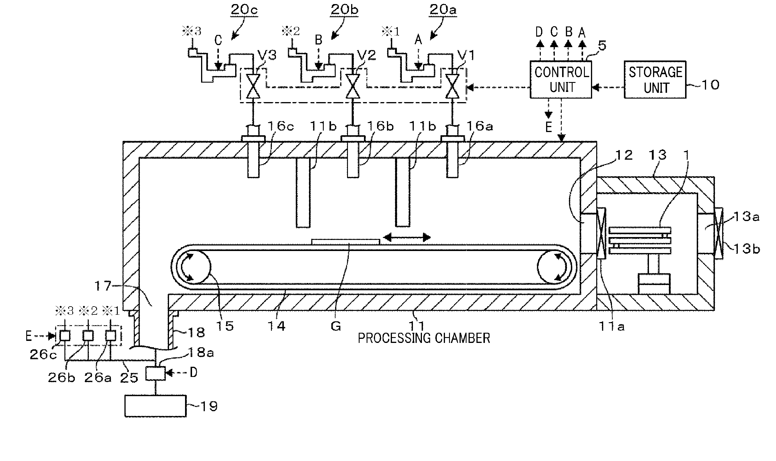
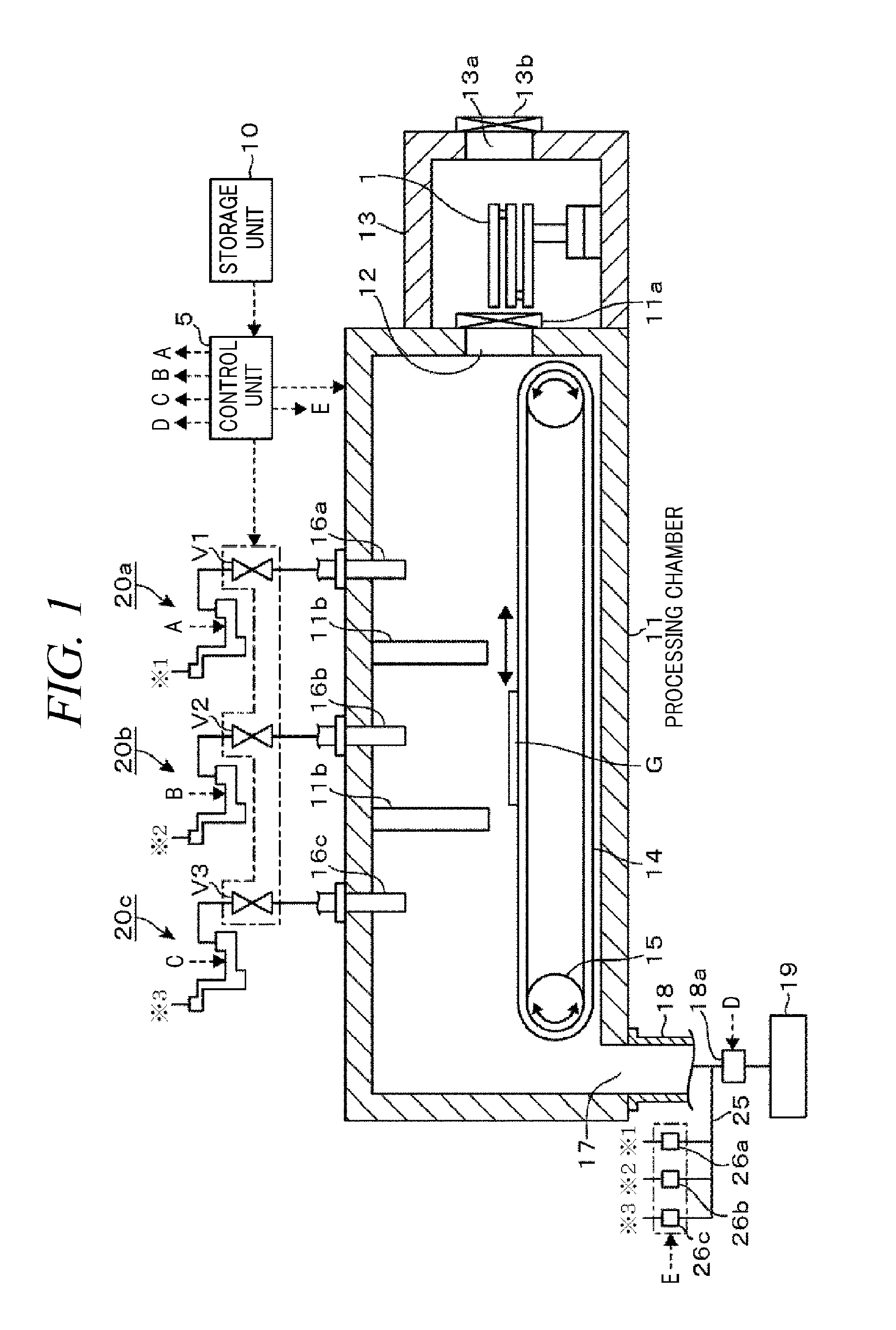
[0025]A film forming apparatus using a source gas generating device in accordance with the present disclosure will be explained with reference to FIG. 1. The film forming apparatus is an evaporating apparatus that has been conventionally utilized to form a film by vapor deposition. The film forming apparatus includes, as illustrated in FIG. 1, a processing chamber 11 maintained under a vacuum atmosphere; and a load lock transfer chamber 13 hermetically connected to the processing chamber 11 via a transfer port 12 and having an arm 1 configured to transfer a substrate G between the atmosphere and the processing chamber 11. In FIG. 1, a reference numeral 13a denotes an opening, and reference numerals 11a and 13b represent gate valves.

[0026]A substrate transfer mechanism 14 such as a belt conveyor is installed on a bottom surface of the processing chamber 11 by being held on a non-illustrated supporting member. The substrate transfer mechanism 14 serves as a mounting table for mounting...


PUM

PropertyMeasurementUnit
temperatureaaaaaaaaaa
sizeaaaaaaaaaa
melting pointaaaaaaaaaa

Abstract

A source gas generating device includes a liquid accommodation unit that accommodates therein the liquid source obtained by liquefying the solid source; a first energy feed unit that supplies energy to raise a temperature of a first region within the liquid accommodation unit to a melting point of the solid source; a second energy feed unit that supplies energy to raise a temperature of a second region within the liquid accommodation unit to a temperature higher than the temperature of the first region, the second region being distanced apart from the first region via a liquid flowing region; a solid source feed unit that supplies the solid source into the first region of the liquid accommodation unit; and an outlet port that discharges the source gas produced by the evaporation of the liquid source within the second region of the liquid accommodation unit.

Description

CROSS-REFERENCE TO RELATED APPLICATION[0001]This application claims the benefit of Japanese Patent Application No. 2008-322852, filed on Dec. 18, 2008, the entire disclosures of which are incorporated herein by reference.FIELD OF THE INVENTION[0002]The present disclosure relates to a source gas generating device that generates a film forming source gas by vaporizing a liquid source produced by liquefying a solid source, and also relates to a film forming apparatus that performs a film forming process by supplying the source gas onto a substrate.BACKGROUND OF THE INVENTION[0003]Along with a liquid crystal display, an organic EL (Electro Luminescence) display using an organic EL material is known as an image display device for use in a FPD (flat panel display) or a cellular phone, for example. In a manufacturing process of such an organic EL display, a source gas is produced through evaporation or sublimation by way of heating a solid source, e.g., an organic EL material containing or...

Claims


Application Information

Patent Timeline
Patent Type & Authority Applications(United States)
IPC IPC(8): C23C16/00
CPCC23C14/243C23C14/246H01L21/205
Inventor TAMURA, AKITAKEHAYASHI, TERUYUKI
Owner TOKYO ELECTRON LTD
Why Eureka
Try Eureka