
Polarizing film, method for producing polarizing film, polarizing plate, method for producing polarizing plate, and Anti-glare vehicular film

Inactive Publication Date: 2010-06-24
FUJIFILM CORP
View PDF3 Cites 38 Cited by
  • Summary
  • Abstract
  • Description
  • Claims
  • Application Information

AI Technical Summary

Benefits of technology

[0019]The present invention is accomplished to solve the above-mentioned conventional problems and to achieve the following objects. The objects of the present invention are to provide a polarizing film which has excellent durability and excellent orientation properties and a small shrinkage stress and is capable of producing a polarizing plate with a large surface area; a method for producing a polarizing film; a polarizing plate; a method for producing a polarizing plate; and related techniques using them
[0022]In light of this situation, as a result of carrying out extensive studies and examinations, the present inventors have found that as a matrix polymer film is made thinner, the orientation properties of dichroic metal nanoparticles (metal nanorods) are improved and thus it is possible to increase the degree of orientation of the dichroic metal nanoparticles (metal nanorods) with a small drawing ratio.
[0026]As a result of carrying out extensive studies and examinations in an attempt to solve the aforesaid problems, the present inventors have found that it is possible to reduce the dimensional change of a polarizing film by making the polarizing film thinner, even when the polarizing film undergoes glass laminating process.
[0038]The present invention can solve the conventional problems described above and achieve the above mentioned objects. Specifically, according to the present invention, it is possible to provide a polarizing film which has excellent durability and excellent orientation properties and a small shrinkage stress and is capable of producing a polarizing plate with a large surface area; a method for producing a polarizing film; a polarizing plate; a method for producing a polarizing plate; and related techniques using them. Also, according to the present invention, it is possible to provide a polarizing film which enables easy adjustment of the optical density and the color tint and is flexible and can be laminated on various types of substrates, a method for producing a polarizing film, a polarizing plate, a method for producing a polarizing plate, and related techniques using them.

Problems solved by technology

In this method, however, a problem arises in that since the thickness of a polarizing film produced is thick, the film is subjected to a large shrinkage stress, resulting in easy occurrence of curling.
It is conceivable that the use of these methods makes it possible to obtain high durability of a resulting polarizing film, however, they have a problem in that metal nanorods in the resulting polarizing film have a low orientation degree (0.8 or lower).
The use of these methods makes it possible to obtain high durability of a polarizing film, however, these methods have problems in that it is difficult to increase the surface area of a polarizing plate using the polarizing film because the film is heated at high temperature during the process of polymerization and stretching, and it is impossible to adjust the optical density and the color tint.
Accordingly, there has not yet been provided a satisfactory polarizing film which has excellent durability and excellent orientation properties and a small shrinkage stress and is capable of producing a polarizing plate with a large surface area.

Method used


Image

  • Polarizing film, method for producing polarizing film, polarizing plate, method for producing polarizing plate, and Anti-glare vehicular film
  • Polarizing film, method for producing polarizing film, polarizing plate, method for producing polarizing plate, and Anti-glare vehicular film
  • Polarizing film, method for producing polarizing film, polarizing plate, method for producing polarizing plate, and Anti-glare vehicular film

Examples


first embodiment

[0277]Firstly, the polarizing film is produced by the method for producing a polarizing film.

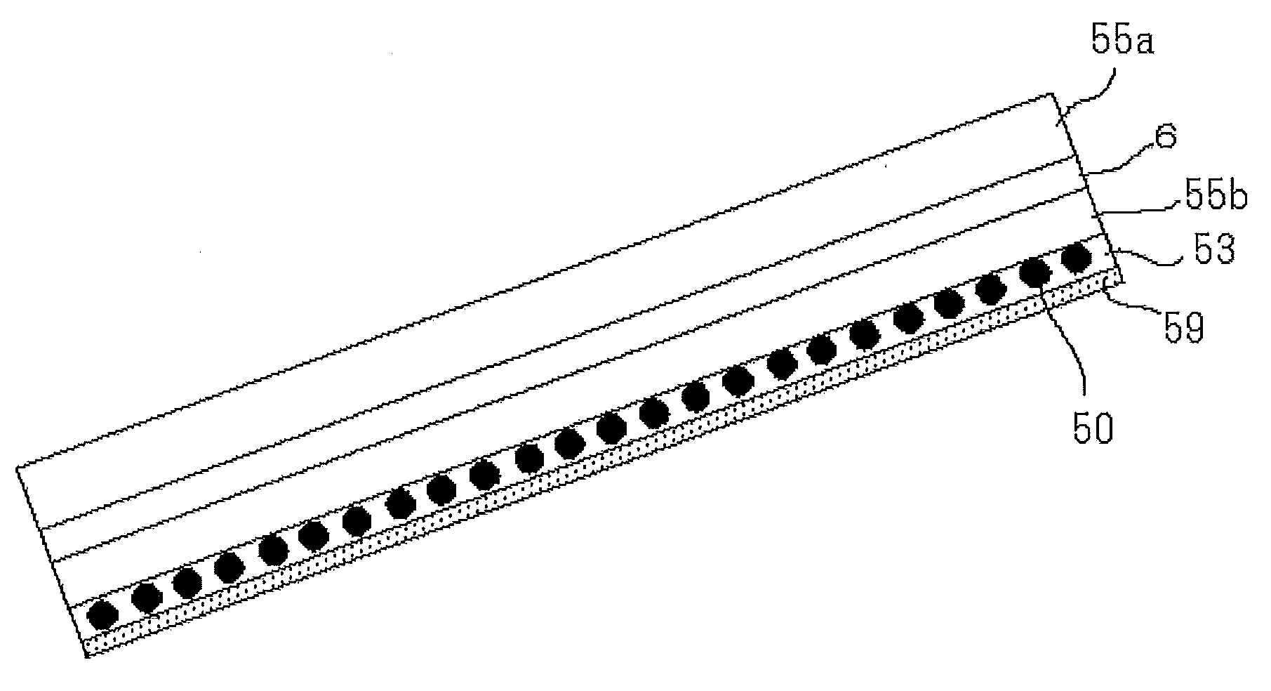
[0278]As for the polarizing film, a composition containing dichroic anisotropic metal nanoparticles 10 is applied onto a stretchable substrate 12 and dried to form a composition layer 11 (refer to FIG. 6A), and the stretchable substrate 12 with the composition layer 11 formed on a surface thereof is stretched together with the composition layer 11, and thereby a polarizing film 13 is obtained on the stretchable substrate 12 (refer to FIG. 6B).

[0279]Next, in a laminate film 17 in which the polarizing film 13 is formed on the stretchable substrate 12, the laminate film 17 is attached to a first base material 14a via an adhesive layer (an adhesive sheet) 16 so that the surface of the laminate film 17 not provided with the stretchable substrate 12 faces the first base material 14a (refer to (FIG. 6C).

[0280]After the attaching, the stretchable substrate 12 is peeled off from the laminate film 17,...

second embodiment

[0286]In a second embodiment of the method for producing a polarizing plate of the present invention, which differs from the first embodiment, a polarizing plate is produced without using an adhesive layer (an adhesive sheet layer).

[0287]Firstly, in the same manner as in the production of the laminate film 17 (refer to FIGS. 6A and 6B) in the first embodiment, a laminate film 27 is produced in which a polarizing film 23 containing dichroic anisotropic metal nanoparticles 20 on a stretchable substrate 22.

[0288]Next, the laminate film 27 is directly attached to a first base material 28a so that the surface of the laminate film 27 not provided with the stretchable substrate 22 faces the first base material 28a (refer to FIG. 7A).

[0289]After the attaching, the stretchable substrate 22 is peeled off from the laminate film 27, and the first base material 28a is laminated on the polarizing film 23 (refer to FIG. 7B).

[0290]Similarly, a first base material 28b is laminated on the surface of ...

third and fourth embodiments

[0296]As to the method for producing a polarizing plate according to the first and second embodiments, the combining step using the second base material is not necessarily required. When the first base material is, for example, the protective film such as a TAC film or a transparent base such as glass plate, the polarizing plate can be produced as the polarizing plate 100 (third embodiment) shown in FIG. 6E in the first embodiment or the polarizing plate 200 (fourth embodiment) shown in FIG. 7C in the second embodiment.

Other Embodiments

[0297]In addition to the above, as the layer configuration of a polarizing plate, the same type of base materials are not necessarily provided on respective surfaces of the polarizing film in the first to fourth embodiments, base materials may be selected depending on the purpose, to be provided on the polarizing film.

[0298]Also, the polarizing plate may be configured to further provide the surface treatment layer such as a reflection preventing layer...


PUM

PropertyMeasurementUnit
Thicknessaaaaaaaaaa
Thicknessaaaaaaaaaa
Thicknessaaaaaaaaaa

Abstract

The present invention provides a polarizing film which contains at least dichroic anisotropic metal nanoparticles and a thermoplastic resin, wherein the polarizing film has a thickness of 12.5 μm or less.

Description

BACKGROUND OF THE INVENTION[0001]1. Field of the Invention[0002]The present invention relates to a polarizing film, a method for producing a polarizing film, a polarizing plate, a method for producing a polarizing plate, and an anti-glare vehicular film.[0003]2. Description of the Related Art[0004]As a production method of a polarizing plate, there has been known a method for producing a polarizing plate using a substance such as iodine and an organic dye. In the production method, a Vinylon film (approximately 75 μm in thickness) is dyed with iodine or an organic dye while being uniaxially stretched between rolls in water, further, PVA (polyvinyl alcohol) is subjected to a film curing treatment with boric acid or the like to produce a polarizing film, and generally, the polarizing film is sandwiched in between TAC (triacetylcellulose) base materials, using PVA paste.[0005]In this method, however, a problem arises in that since the thickness of a polarizing film produced is thick, t...

Claims


Application Information

Patent Timeline
IPC IPC(8): G02B5/30B29D11/00
CPCB29C55/023B29K2029/00B29K2031/04B29K2105/162B29K2995/0034B32B17/10036B32B17/10458B32B17/10788B60J3/06B82Y20/00G02B5/189G02B5/3058G02B2207/101B32B17/10761
Inventor MATSUNAMI, YUKIKATAGIRI, KENSUKEKAMADA, KOH
Owner FUJIFILM CORP
Learn More