Resolution improvement in emission optical projection tomography

a technology of optical projection and emission tomography, applied in the field of optical projection tomography, can solve the problems of preventing the use of samples for further analysis, time-consuming techniques, and inability to accommodate the absorbing molecular markers commonly used, and achieve the effect of reducing blur

Inactive Publication Date: 2010-06-24
HOSPITAL FOR SICK CHILDREN
View PDF12 Cites 7 Cited by
  • Summary
  • Abstract
  • Description
  • Claims
  • Application Information

AI Technical Summary

Benefits of technology

[0021]According to one aspect, there is provided a method of reduci

Problems solved by technology

Unfortunately this technique cannot accommodate absorbing molecular markers commonly used with brightfield microscopy.
Unfortunately, these techniques are time consuming and prevent the use of the sample for further analysis by other means.
Although OPT provides for effective imaging, reconstructed OPT images suffer from blurring that worsens with increasing distance from the rotational axis of the specimen or sample.
This out-of-focus data is included in the filtered back projection reconstruction process used to construct the resultant 3D vol

Method used


Image

  • Resolution improvement in emission optical projection tomography
  • Resolution improvement in emission optical projection tomography
  • Resolution improvement in emission optical projection tomography

Examples


Embodiment Construction

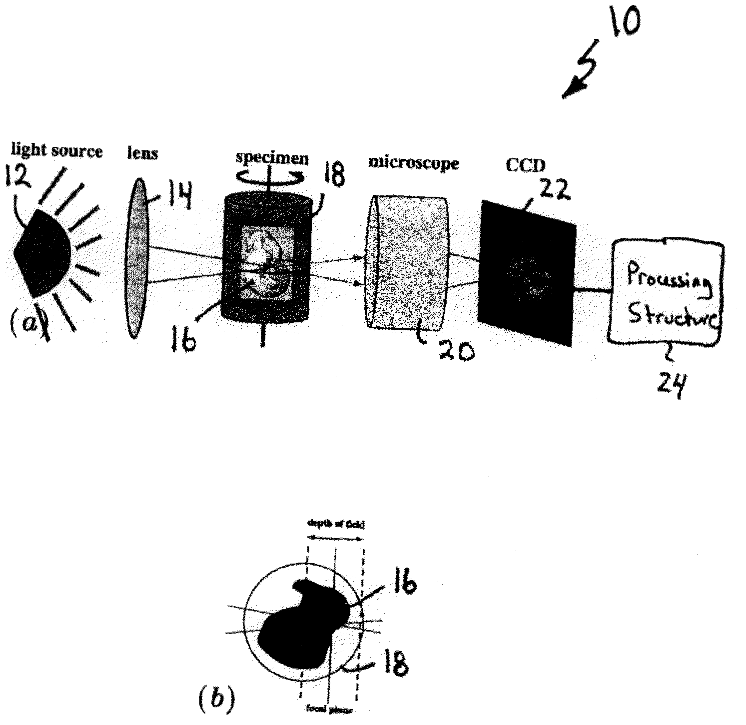
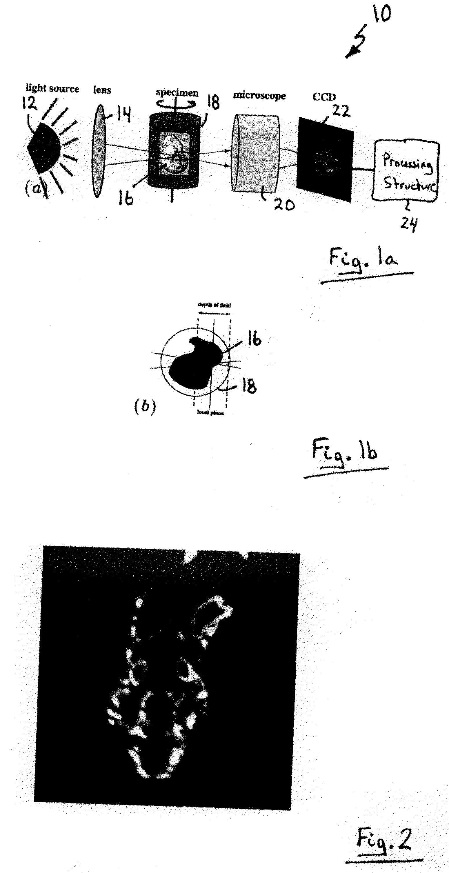
[0061]Turning now to FIG. 1 a, an optical projection tomography (OPT) apparatus is shown and is generally identified by reference numeral 10. As can be seen, OPT apparatus 10 comprises a light source 12, in this embodiment a mercury vapour arc lamp, that directs widefield illumination towards a lens 14. The lens 14 in turn focuses the widefield illumination onto a specimen 16 within a container 18. The container 18 has optically flat parallel windows and contains a 1:2 mixture of benzyl alcohol and benzyl benzoate (BABB) therein. The container 18 is rotatable about an axis of rotation that is perpendicular to the optical axis of the OPT apparatus 10 to enable the specimen 16 to be imaged at multiple angles. In this embodiment, the specimen is small (1 cc) and semi-transparent and is embedded in agarose. The refractive index of the embedded specimen is matched with the BABB mixture within the container 18.

[0062]Fluorescent photons emitted from fluorophores throughout the specimen 16 ...


PUM


Abstract

A method of reducing blur in an optical projection tomography (OPT) image comprises filtering the frequency space information of OPT image data to reduce the effects of out-of-focus data and defocused in-focus data and reconstructing the filtered OPT data.

Description

CROSS-REFERENCE TO RELATED APPLICATIONS[0001]This application claims the benefit of U.S. Provisional Application Ser. No. 60 / 845,497 filed on Sep. 19, 2006 for an invention entitled “Resolution Improvement In Emission Projection Tomography”, the content of which is incorporated herein by reference.FIELD OF THE INVENTION[0002]The present invention relates generally to optical projection tomography and in particular to a method of reducing blur in optical projection tomography images and to an optical projection tomography apparatus.BACKGROUND OF THE INVENTION[0003]Rapid advances in genetic research using animal models have driven the demand for three-dimensional (3D) biological imaging of small specimens. Three-dimensional visualization of whole organs or organisms is often used to gain a better understanding of the development of complex anatomy. Information pertaining to the time and location of gene expression throughout a complete organism is also crucial for understanding develo...

Claims


Application Information

Patent Timeline
IPC IPC(8): G06K9/00
CPCG01N21/4795
Inventor HENKELMAN, R. MARKWALLS, JONATHAN R.
Owner HOSPITAL FOR SICK CHILDREN
Why Eureka
Try Eureka