Method and device for intermediate superheating in solar direct evaporation in a solar-thermal power plant

a solar thermal and power plant technology, applied in the direction of machines/engines, solar heat generation using solar energy, lighting and heating apparatus, etc., can solve the problems of high pressure loss, inability to operate the conventional power plant part to the optimal, and inability to achieve intermediate superheating, etc., to achieve the effect of low pressure loss, high concentration factor and high process temperatur

Inactive Publication Date: 2010-07-01
SIEMENS AG
View PDF2 Cites 23 Cited by
  • Summary
  • Abstract
  • Description
  • Claims
  • Application Information

AI Technical Summary

Benefits of technology

[0025]Especially advantageously the thermo-solar power plant installation comprises parabolic trough collectors, which are technologically highly mature and have the highest concentration factor for linear-concentrating systems, which makes higher process temperatures possible.
[0026]In an alternate embodiment fresnel collectors are used. An advantage of fresnel col

Problems solved by technology

The conventional power plant part cannot be operated to the optimum with the steam parameters obtained in a solar array with direct evaporation.
However this versi

Method used


Image

  • Method and device for intermediate superheating in solar direct evaporation in a solar-thermal power plant
  • Method and device for intermediate superheating in solar direct evaporation in a solar-thermal power plant
  • Method and device for intermediate superheating in solar direct evaporation in a solar-thermal power plant

Examples


Embodiment Construction

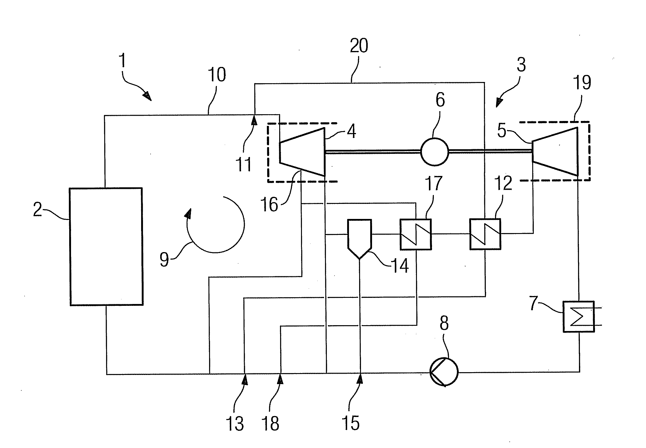
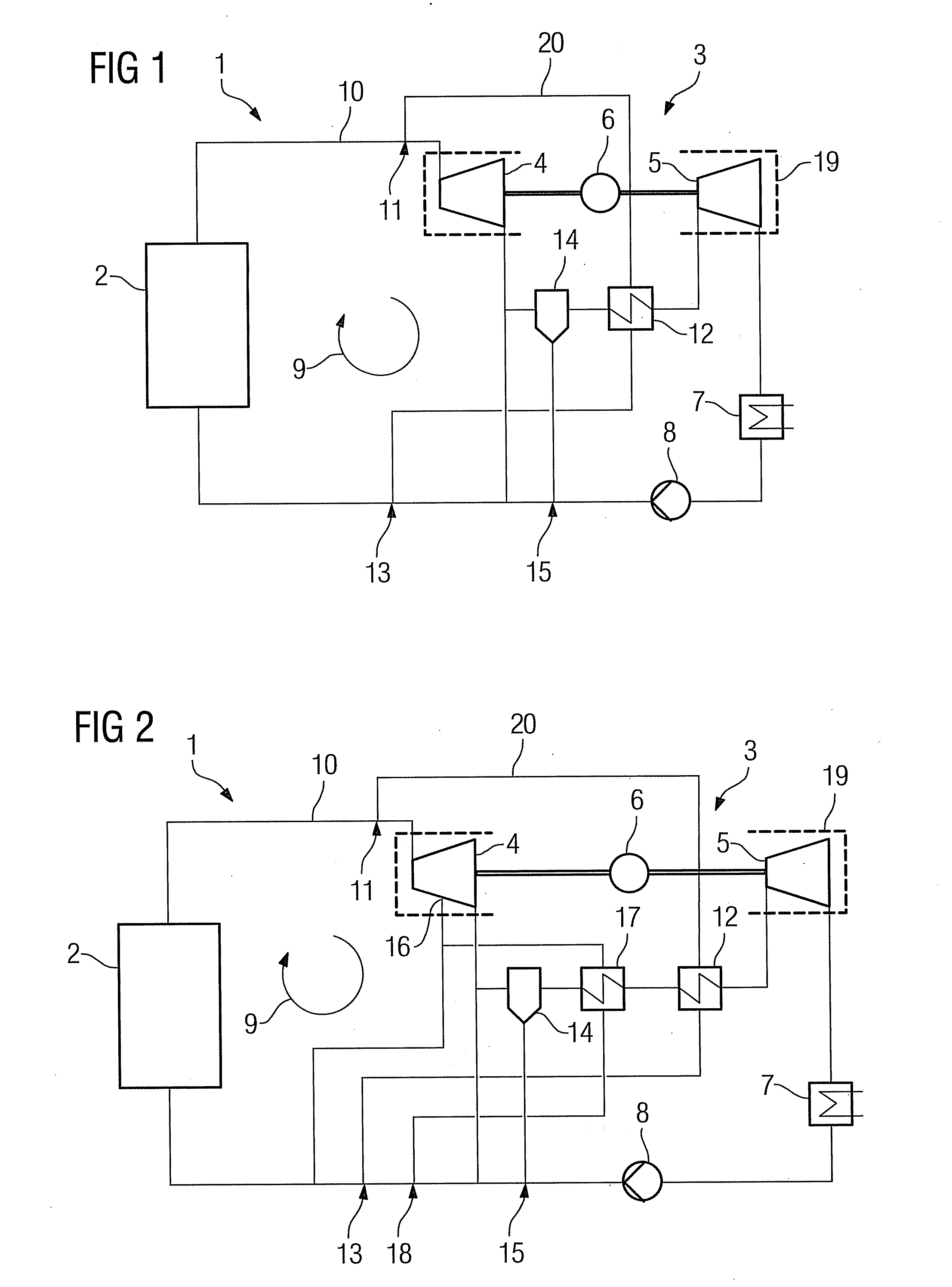
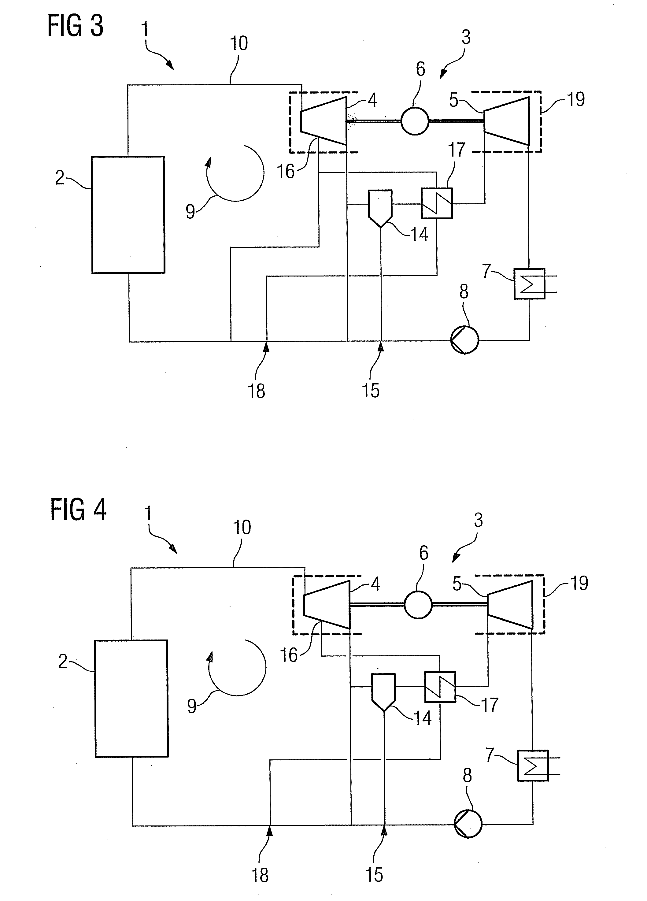
[0040]FIG. 1 shows the schematic structure and the circulation process of a solar-thermal power plant system 1 with direct evaporation according to the invention. The system 1 comprises a solar array, in which the solar radiation is concentrated and converted into thermal energy and can typically feature parabolic trough collectors, solar towers, paraboloid mirror or fresnel collectors. Concentrated solar radiation is output to a heat carrier medium which is evaporated and is introduced as working fluid via a fresh steam line 10 into a relief path 19, consisting of a steam turbine 3. The steam turbine 3 comprises a high-pressure turbine 4 and a low-pressure turbine 5, which drive a generator 6. The working fluid is condensed in the turbine and subsequently evaporated in a condenser 7. A feed water pump 8 pumps the evaporated heat carrier medium back again into the solar array 2, with the circuit 9 of the heat carrier medium or the working fluid respectively being closed.

[0041]In the...


PUM


Abstract

A solar-thermal power plant is provided. The solar-thermal power plant includes a working fluid circuit, a solar steam generator based on direct evaporation and a steam turbine for relieving the working fluid on a relief path while the working fluid supplies technical work. The solar-thermal power plant also includes at least one intermediate superheater, which can be heated using the working fluid. The working fluid may be removed from the circuit upstream of the intermediate superheater and superheated using the working fluid thereof, which can be fed downstream of the heating removal using the relief path. A method for operating a solar-thermal power plant is also provided.

Description

CROSS REFERENCE TO RELATED APPLICATIONS[0001]This application is the US National Stage of International Application No. PCT / EP2008 / 053205, filed Mar. 18, 2008 and claims the benefit thereof. The International Application claims the benefits of German application No. 10 2007 013 852.2 DE filed Mar. 20, 2007, both of the applications are incorporated by reference herein in their entirety.FIELD OF INVENTION[0002]The invention relates to a method for operating a solar-thermal power plant in which a working fluid circulates in a circuit, with a solar steam generator based on direct evaporation and a steam turbine in which the working fluid is expanded while doing technical work on a relief path, with at least one intermediate superheater, which is heated means of working fluid removed from the circuit upstream of the intermediate superheater and which superheats working fluid by means of an intermediate superheater which can be fed downstream of the heating removal by flowing into the re...

Claims


Application Information

Patent Timeline
IPC IPC(8): F03G6/00
CPCF01K3/188F01K7/22F01K7/223Y02E10/46F22B1/003F22B1/006F22G1/12F03G6/003
Inventor BIRNBAUM, JURGENFICHTNER, MARKUSHABERBERGER, GEORGZIMMERMANN, GERHARD
Owner SIEMENS AG
Why Eureka
Try Eureka