Methods and apparatus for safe application of an intubation device

a technology of intubation device and safe application, which is applied in the direction of calibration apparatus, instruments, catheters, etc., can solve the problems of suffocating patients, internal bleeding or death of patients, and inability to accurately maintain the pressure in the cu

Inactive Publication Date: 2010-07-01
SINGH MANU B
View PDF3 Cites 90 Cited by
  • Summary
  • Abstract
  • Description
  • Claims
  • Application Information

AI Technical Summary

Benefits of technology

[0012]The pump, tubing, and cuff form an air-tight (i.e., closed) inflation system that accurately maintains pressure in the cuff once the cuff is inflated. The sensor can include a pressure sensor located anywhere within the air-tight inflation system and report the pressure in a human- or machine-readable form, optionally as “go” or “no go” discrete states or as an actual pressure reading. Alternatively, the pressure sensor may be located on the surfac...

Problems solved by technology

Intubation is a potentially dangerous invasive procedure with many plausible errors when performed improperly.
Over-inflation of the cuff can result in a patient's internal bleeding or, potentially, death.
Another example of a common intubation error is the insertion of the intubation tube in the wrong lumen, potentially suffocating the patient.
As mentioned above, over-inflation of the cuff(s) may result in complications, and the complications may manifest themselves as mucosal bleeding and ischemia, esophageal or tracheal bleeding, or death.
Such image systems are not generally u...

Method used


Image

  • Methods and apparatus for safe application of an intubation device
  • Methods and apparatus for safe application of an intubation device
  • Methods and apparatus for safe application of an intubation device

Examples


example device

Configurations

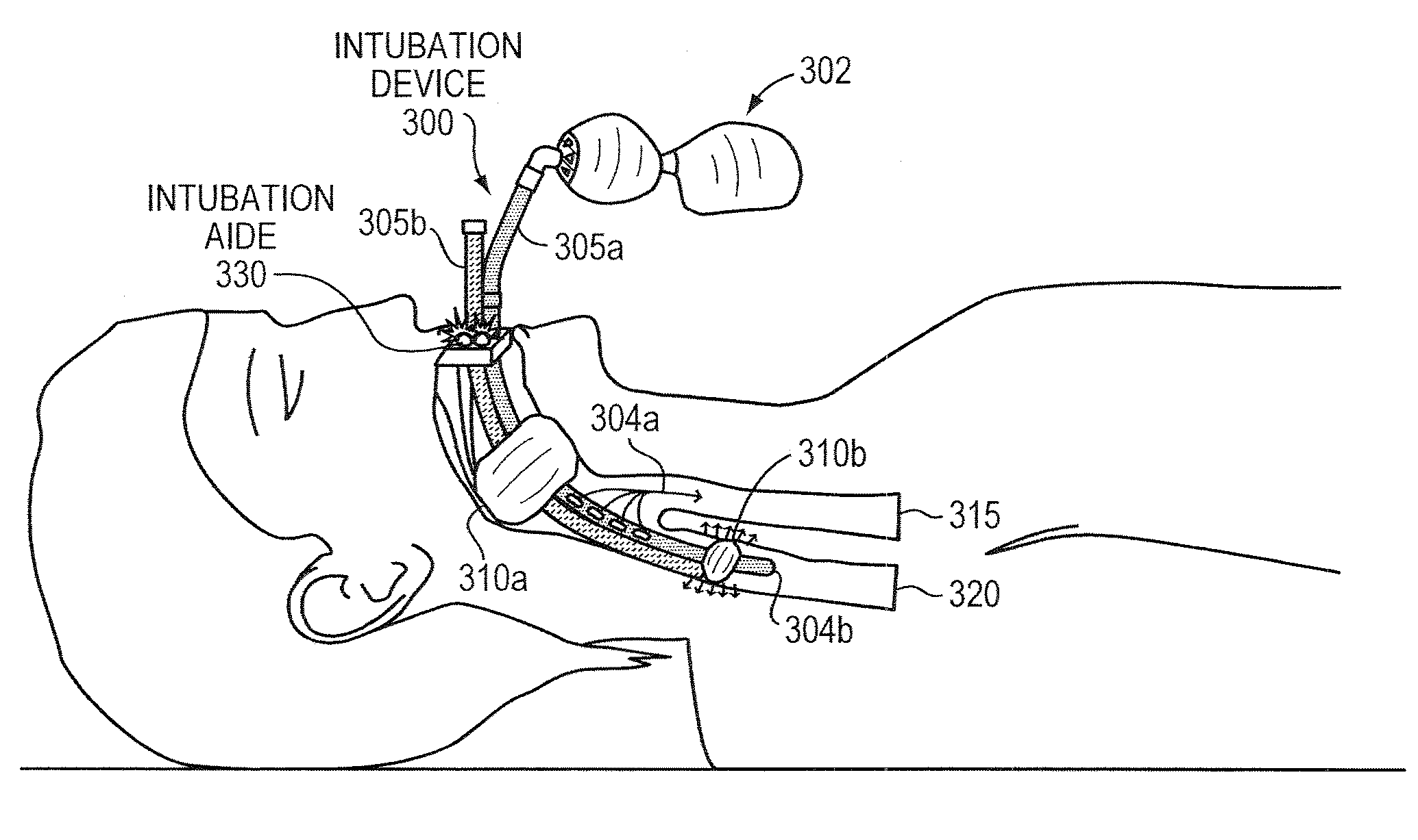
[0081]Intubation devices according to some embodiments of the present invention comprise at least one sensor such as a pressure sensor or a force sensor, at least one air pump, connectors, tubing, tubing connectors, air release valve(s), circuitry such as logic gates, microcontrollers, op-amps, transistors, resistors, and the like, a user interface, and a power source such as a battery pack, over-charged capacitor, or lithium, alkaline batteries, or the like.

[0082]In some embodiments, the intubation devices of the present invention are portable. In some embodiments, the intubation devices according to the present invention may further comprise operational indicators such as lights, sound speakers, or LCD screen, transmitter to transmit data to an external device, receiver to receive data or commands from an external device, and buttons or switches.

[0083]It should be understood that components and corresponding methods beyond basic intubation tube(s) with associated lum...

experiment 1

[0093]Pump Controller

[0094]Step 1a Pressure Sensor calibration: A MPX5050 Integrated Silicone Pressure Sensors was tested with a manometer to verify that the voltage output correctly followed Voltage Output=Vcc*(0.018*Pressure+ / −0.04).

[0095]Step 1b Force sensor calibration: Tekscan Flexiforce Piezoresistive Force Sensor(s) were calibrated using small weights, measured in increments of 5 grams, and an inverting amplifier, used to verify that it follows Voltage output=−Voltage Input (Fixed Resistance / Flexiforce variable resistance).

[0096]Step 2 Pump Controller Analyzer calibration: The pump controller analyzer, employing a comparator, was tested with an input voltage that matched the expected voltage from the pressure or force sensor(s). The analyzer gave an output voltage changing from +Vcc to 0 volts, once the expected voltage was inputted.

[0097]Step 3 Pressure or Force Sensors and Pump Controller's Analyzer: The pressure or force sensor(s) were tested together along with the pump c...

experiment 2

[0106]In order to determine the use of this technology in human beings, the following experiment was conducted in an animal model. Pigs were utilized, as they have similar respiratory system to other mammalian species.

[0107]Two pigs were utilized in each of the two experiments (Experiment 2A and Experiment 2B). The pigs were initially sedated with Telazol 4.4 mg / kg and Xylazine 2.2 mg / kg, and maintained sedation with 2.00% Isoflurane.

[0108]Experiment 2A—employed each of the designed tubes measuring the forces in the fore and aft sides of the cuff using the Flexiforce piezoresistive force sensors (with the output measured in resistance, but converted to conductance to illustrate force increase) in both the trachea and esophagus. All of the designed tubes were tested by filling their cuffs to their maximal volume; the respective maximum volumes values were as follows: 100 ml and 15 ml for the proximal and distal cuff of the resuscitation tube, 60 ml for the connected cuffs of the tran...


PUM


Abstract

Intubation is a potentially dangerous invasive procedure with many plausible errors, such as over-inflation of a cuff and insertion of an intubation tube in the wrong lumen, potentially resulting in a patient's internal bleeding, suffocation, or even death. An intubation aide according to example embodiments of the present invention allows intubation of a patient, while eliminating potential injury to the patient, increasing accuracy and reliability of the placement of the intubation tube, and drastically decreasing procedural time. Within moments of insertion of the device into a patient, the medical caregiver knows, with complete certainty, the location of the intubation device without applying traditional time-consuming tasks. Embodiments also provide patient safety, if intubated for a prolonged periods, by regulating an inflation pressure of the cuff. The intubation aide can also be used for training purposes and is ideal for intubation in hospital and field settings.

Description

RELATED APPLICATION(S)[0001]This application claims the benefit of U.S. Provisional Application No. 61 / 141,746, filed on Dec. 31, 2008. The entire teachings of the above application are incorporated herein by reference.BACKGROUND OF THE INVENTION[0002]Intubation is the placement of an intubation tube of an intubation device into a lumen (i.e., trachea or esophagus) of the body of a subject in order to provide ventilation by mechanical or artificial means via the intubation tube. Intubation can be in the form of tracheal intubation, which is the placement of a tube into the trachea of a subject, as well as esophageal intubation, which is the placement of a tube into the esophagus of a subject.[0003]Intubation is a potentially dangerous invasive procedure with many plausible errors when performed improperly. An example of an intubation error is over-inflation of a cuff, where the cuff is an inflatable bulb coupled to an exterior wall of the intubation tube and used to maintain a posit...

Claims


Application Information

Patent Timeline
IPC IPC(8): A61M16/04G01D18/00A61F2/958
CPCA61M16/04A61M16/0486A61M16/044A61M16/0488A61M2205/17A61M2205/332A61M2205/3331A61M2205/3553A61M2205/3592A61M2205/581A61M2205/583A61M2205/70A61M2209/02G09B23/288A61M16/0409A61M16/0415A61M16/0459A61M16/0003A61M2016/0027A61M2205/35A61M2205/50A61M2209/06A61M16/0411A61M25/10184A61M16/0406A61M16/0438A61M16/0434
Inventor SINGH, MANU B.
Owner SINGH MANU B
Why Eureka
Try Eureka