Heat exchanger assembly

Inactive Publication Date: 2010-07-01
RAYTHEON CO
View PDF6 Cites 13 Cited by
  • Summary
  • Abstract
  • Description
  • Claims
  • Application Information

AI Technical Summary

Benefits of technology

[0007]It is a further object of this invention to provide such a heat exchanger assembly which does not suffer from galvanic corrosion.
[0008]It is a further object of the subject invention to provide such an assembly which exhibits improved reliability.
[0010]It is a further object of the subject invention to provide such an assembly which can be manufactured easily and at a lower cost.
[0011]It is a further object of the subject invention to provide such a heat exchanger assembly which can be made lighter.
[0014]It is a further object of the subject invention to provide such an improved heat exchanger assembly which acts as a synergistic structure, providing both improved structural and thermal dissipation properties.
[0016]The invention results from the partial realization that, in one example, all the materials used in a heat exchanger (e.g., a cold plate) can be the same to prevent galvanic corrosion if metal foam is used as the wick and stir welding is used to hermetically seal the vapor chamber in which the metal foam resides.

Problems solved by technology

One problem with copper is that it is heavy which is a concern in ship and airborne applications.
Historically, aluminum can be used for the cold plate housing, allowing weight optimization, but when integrated with the copper heat pipe can introduce the possibility for galvanic corrosion.
When solder, or other materials, are used as the barrier material between the cold plate housing and heat pipe, voids introduce thermal resistances, contribute to local galvanic corrosion opportunity, and reliability problems.
Moreover, the current process of making the cold plates limits design flexibility and is labor intensive and expensive.
Copper is also becoming increasingly costly.
Aluminum heat pipes available on the market today suffer from reduced thermal efficiency.
When integrated with aluminum cold plates, the dissimilar metal problem is solved and the possibility for galvanic corrosion is reduced to, but the result is reduced thermal performance.
This reduced performance limits applications.
Additionally, these heat pipes suffer from poor reliability and manufacturability issues.
Attempts at plating either aluminum or copper cold plates and copper heat pipes with a tin-lead composition to eliminate corrosion resulted in additional thermal interfaces, an added expense, and additional manufacturing steps.

Method used


Image

  • Heat exchanger assembly
  • Heat exchanger assembly
  • Heat exchanger assembly

Examples


Embodiment Construction

[0042]Aside from the preferred embodiment or embodiments disclosed below, this invention is capable of other embodiments and of being practiced or being carried out in various ways. Thus, it is to be understood that the invention is not limited in its application to the details of construction and the arrangements of components set forth in the following description or illustrated in the drawings. If only one embodiment is described herein, the claims hereof are not to be limited to that embodiment. Moreover, the claims hereof are not to be read restrictively unless there is clear and convincing evidence manifesting a certain exclusion, restriction, or disclaimer.

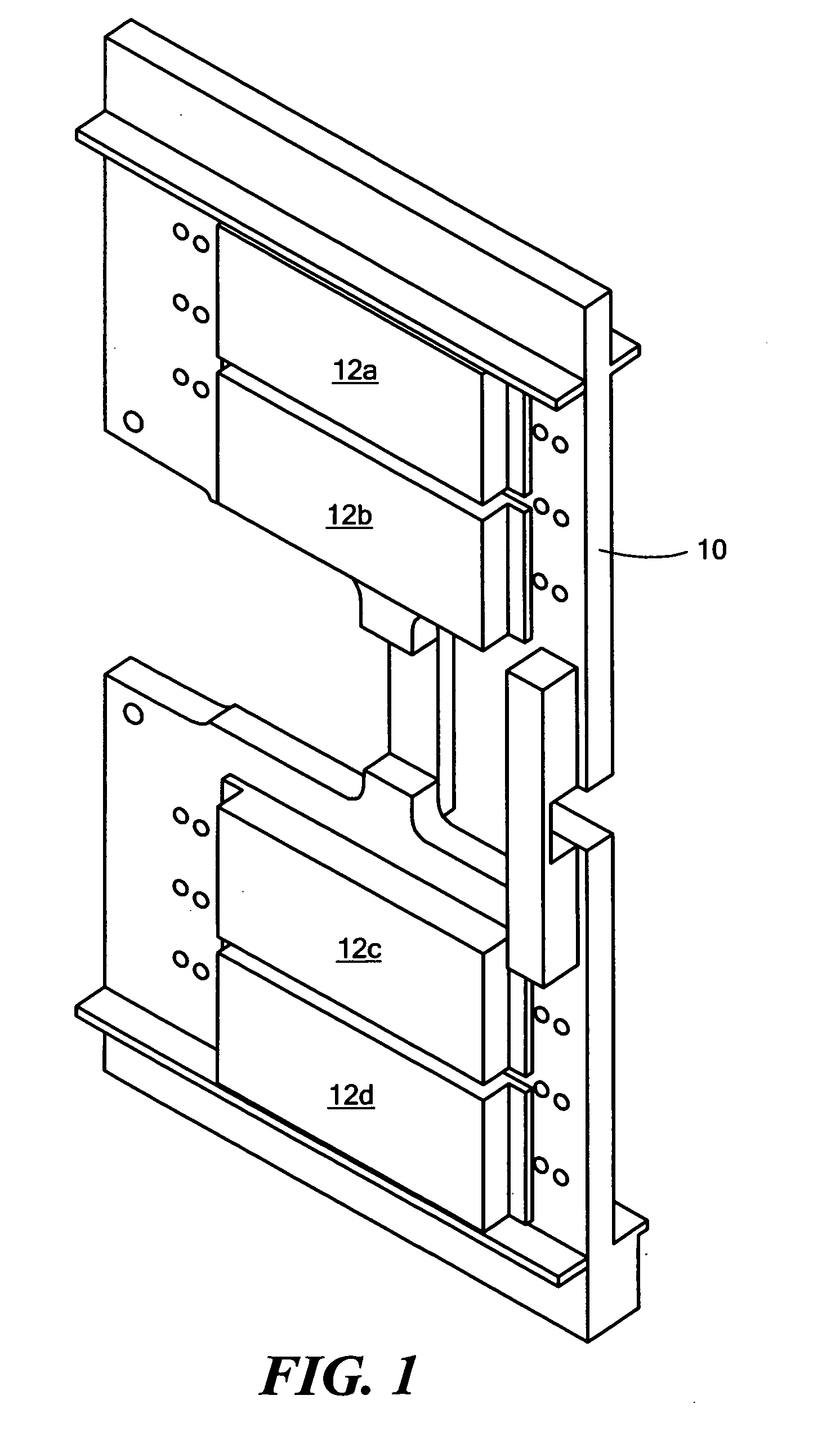
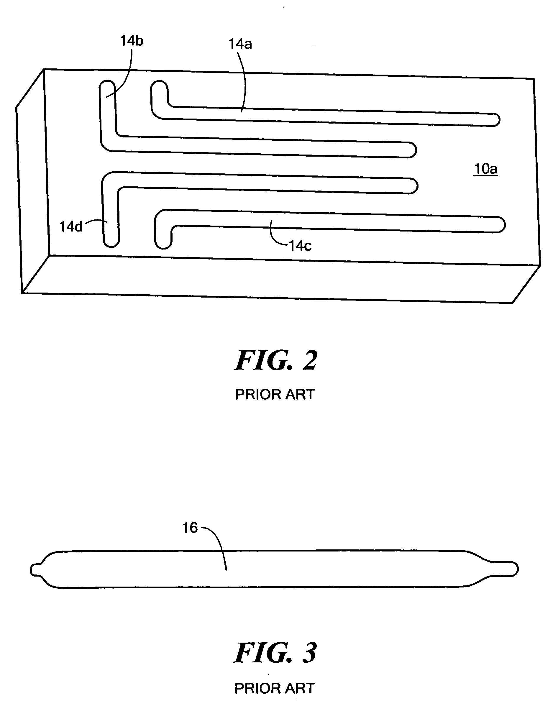
[0043]There is shown in FIG. 1 an example of a prior art cold plate 10 for radar transmit and receive modules 12a-12d. Cold plate 10 typically includes two halves one of which is schematically shown in FIG. 2. Cold plate half 10a, typically made of aluminum, is machined to form channels as shown at 14a-14b then nickel under...


PUM

PropertyMeasurementUnit
Shapeaaaaaaaaaa
Electrical conductoraaaaaaaaaa

Abstract

An improved heat exchanger assembly and method. First and second plates made of a predetermined thermally conductive material are configured when mated to form a hermetically sealed vapor chamber. A wick made of the same predetermined thermally conductive material resides in the vapor chamber forming a gas chamber.

Description

FIELD OF THE INVENTION[0001]The subject invention relates to heat transfer, heat exchanger assemblies, and cold plates.BACKGROUND OF THE INVENTION[0002]Heat exchangers are used to cool electronic components generating heat. In one example, a cold plate assembly used in connection with radar transmit and receive modules is made of aluminum and includes therein copper heat pipes.[0003]One problem with copper is that it is heavy which is a concern in ship and airborne applications. Historically, aluminum can be used for the cold plate housing, allowing weight optimization, but when integrated with the copper heat pipe can introduce the possibility for galvanic corrosion. When solder, or other materials, are used as the barrier material between the cold plate housing and heat pipe, voids introduce thermal resistances, contribute to local galvanic corrosion opportunity, and reliability problems. Moreover, the current process of making the cold plates limits design flexibility and is labo...

Claims


Application Information

Patent Timeline
IPC IPC(8): F28D15/00B21D53/02
CPCY10T29/49353F28D15/046
Inventor NELSON, N. D.MILANO, VINCENT J.BENINATI, GREGORY G.GODDARD, CAMERON B.THOREN, MATTHEW D.HOLMES, EDWARD I.
Owner RAYTHEON CO
Why Eureka
Try Eureka