Method and device for measuring the condition of steel structures

a technology for structural condition and measurement method, applied in the direction of liquid/fluent solid measurement, instrument, material electrochemical variable, etc., can solve the problems of mechanical stress that can arise unintentionally during construction, long transient time, and limited possibilities, so as to improve the detection sensitivity of micro cracks, improve the estimation of crack position, and improve the effect of sensitivity and accuracy

Active Publication Date: 2010-07-01
HORN GMBH & CO KG
View PDF8 Cites 16 Cited by
  • Summary
  • Abstract
  • Description
  • Claims
  • Application Information

AI Technical Summary

Benefits of technology

[0031]Thus, the transient potential drop provides information about both the permeability and the conductivity of the material, which are influenced by mechanical stress and fatigue condition. The electrical resistance is influenced by conductivity and geometry, which again is influenced by metal loss corrosion and erosion and cracks. The different defects have different influences on different parts of the voltage response curve, and by observing the entire response curve, both the transient and the stationary part, sensitivity and accuracy can both be improved compared with the other two mentioned patents.
[0032]By observing the entire voltage drop response curve for crack monitoring, significantly improved detection sensitivity for micro cracks on the surface is obtained because of much higher current density

Problems solved by technology

Large steel structures are often subjected to varying loads causing deterioration.
Mechanical stress can arise unintentionally both during construction, (for example in or adjacent to weld seams) and during operation because of uncontrollable conditions.
By using of such methods changes are measured from the instant the arrangement is installed with respect to absolute mechanical stresses the possibilities are more limited.
Thus, according to the patent a prejudice exists against the consideration of the transient portion of the voltag

Method used


Image

  • Method and device for measuring the condition of steel structures
  • Method and device for measuring the condition of steel structures
  • Method and device for measuring the condition of steel structures

Examples


Embodiment Construction

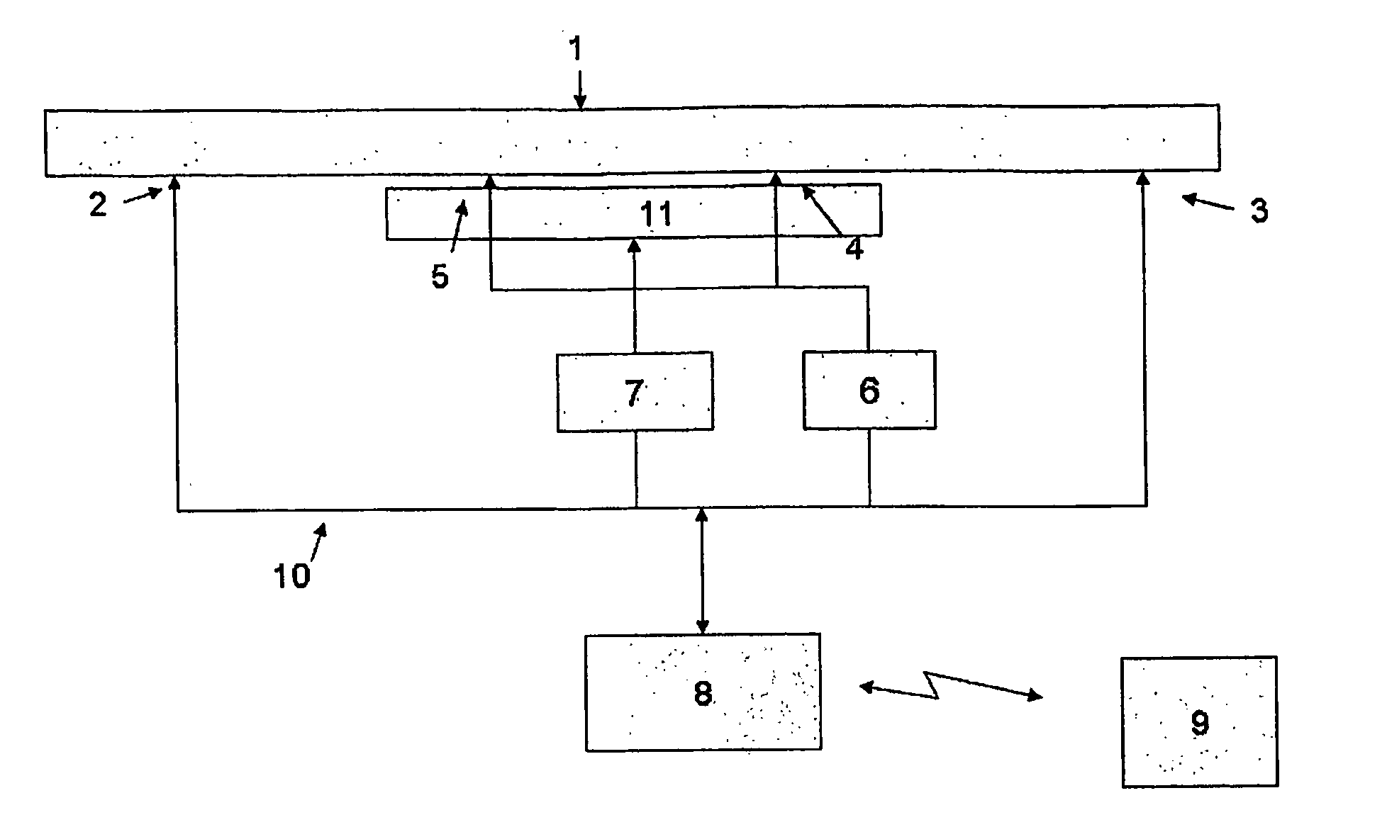
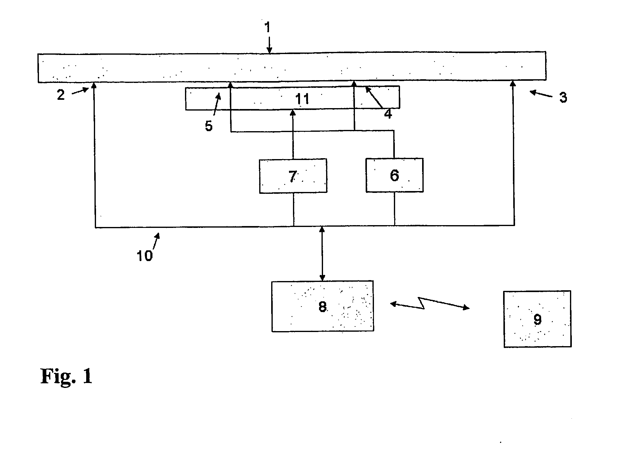
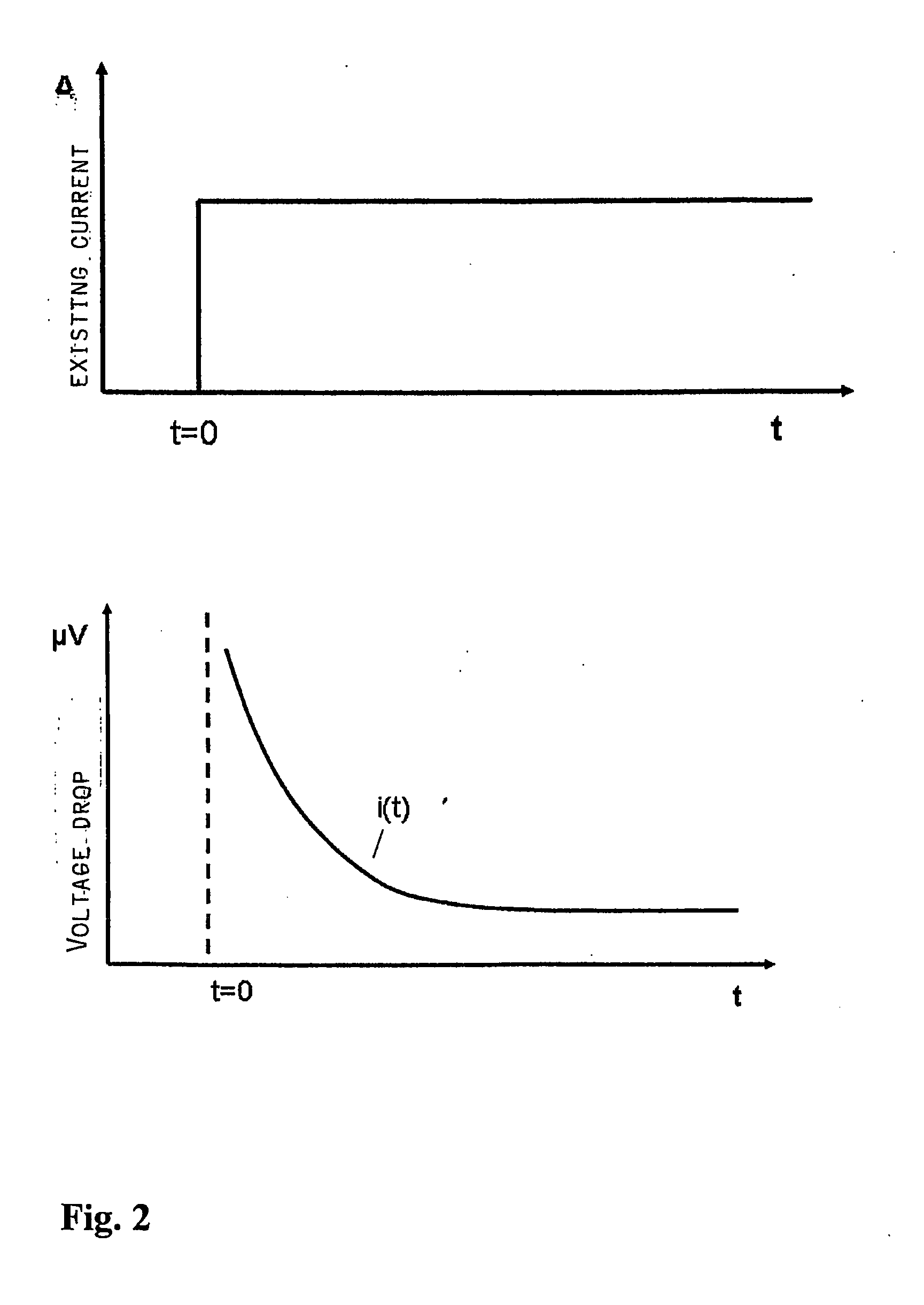
[0041]To the steel plate 1 in FIG. 1 current pulses (excitation current) is applied by means of the source of current in an instrument 8 through contact points 2,3. When required the source of current in 8 alternatively can be used for demagnetization. Such alternatives can be selected by a menu system in the instrument. By means of this source of current there is applied an alternating current with a amplitude diminishing to zero when used for demagnetization. The potential drop a(t) which is measured between measurement points 4,5 is fed to a signal condition circuit 6 that amplifies and digitises voltages and data is intermediately stored for later transfer to instrument 8 for preliminary processing and for later transfer and further processing in a computer 9. The program in computer 9 has an algorithm for analysing the voltage drop response to calculate mechanical stress and / or fatigue and / or cracks and / or metal loss in the monitored material.

[0042]By means of an electromagnet ...


PUM


Abstract

Method and apparatus for measuring parameters in ferromagnetic steel structures, e.g. railway rails and drill pipes, to detect mechanical stress, damage and deterioration. On the monitored structure, devices for magnetization or demagnetization e.g. an electromagnet, will be installed. Two or more electrodes for feeding of a pulse shaped electrical voltage are installed. Across another pair of electrodes, a voltage response signal is measured, and compared with another response signal measured under known conditions or compared with calibration data for the structure. The deviation between these voltages is analyzed to quantify the relative or absolute deviations, and the condition of the steel structure is estimated. The device can measure the transient voltage curves with reference to one or more of the magnetization curves and includes algorithms for analyzing the voltage response curve for determination of mechanical stress and/or fatigue and/or cracks and/or metal loss in steel materials.

Description

BACKGROUND OF THE INVENTION[0001]The present invention is directed to a method for measuring the condition of a steel structure. Furthermore, it comprises a device for carrying out such measurements of condition of a steel structure. The method can be adapted for detection of mechanical stress, fatigue and metal loss e.g caused by corrosion.[0002]More particularly the invention concerns a method for measuring the condition of a steel structure, whereby a pulse-shaped electrical current is applied to the steel through a pair of contact points, generating potential drop curves between another pair of contact points measured by repeated sampling. The steel subjected to the measurements can both be magnetized and demagnetized by means of arrangements known per se and being employed for magnetization of the steel to selected points at the initial, the anhysteretic and hysteretic magnetization curves. Comparison of the potential drop curves at different magnetization makes it possible to ...

Claims


Application Information

Patent Timeline
IPC IPC(8): G01N27/26G01NG01N27/20
CPCG01N27/20
Inventor HORN, HARALD
Owner HORN GMBH & CO KG
Why Eureka
Try Eureka