
Methods for reducing gate dielectric thinning on trench isolation edges and integrated circuits therefrom

a technology of integrated circuits and dielectric thinning, which is applied in the direction of basic electric elements, electrical equipment, semiconductor devices, etc., can solve the problems of gate oxide failure, higher leakage current, and loss of yield or reliability, and achieve the effect of reducing the oxidation rate of the edg

Active Publication Date: 2010-07-01
TEXAS INSTR INC
View PDF1 Cites 11 Cited by
  • Summary
  • Abstract
  • Description
  • Claims
  • Application Information

AI Technical Summary

Benefits of technology

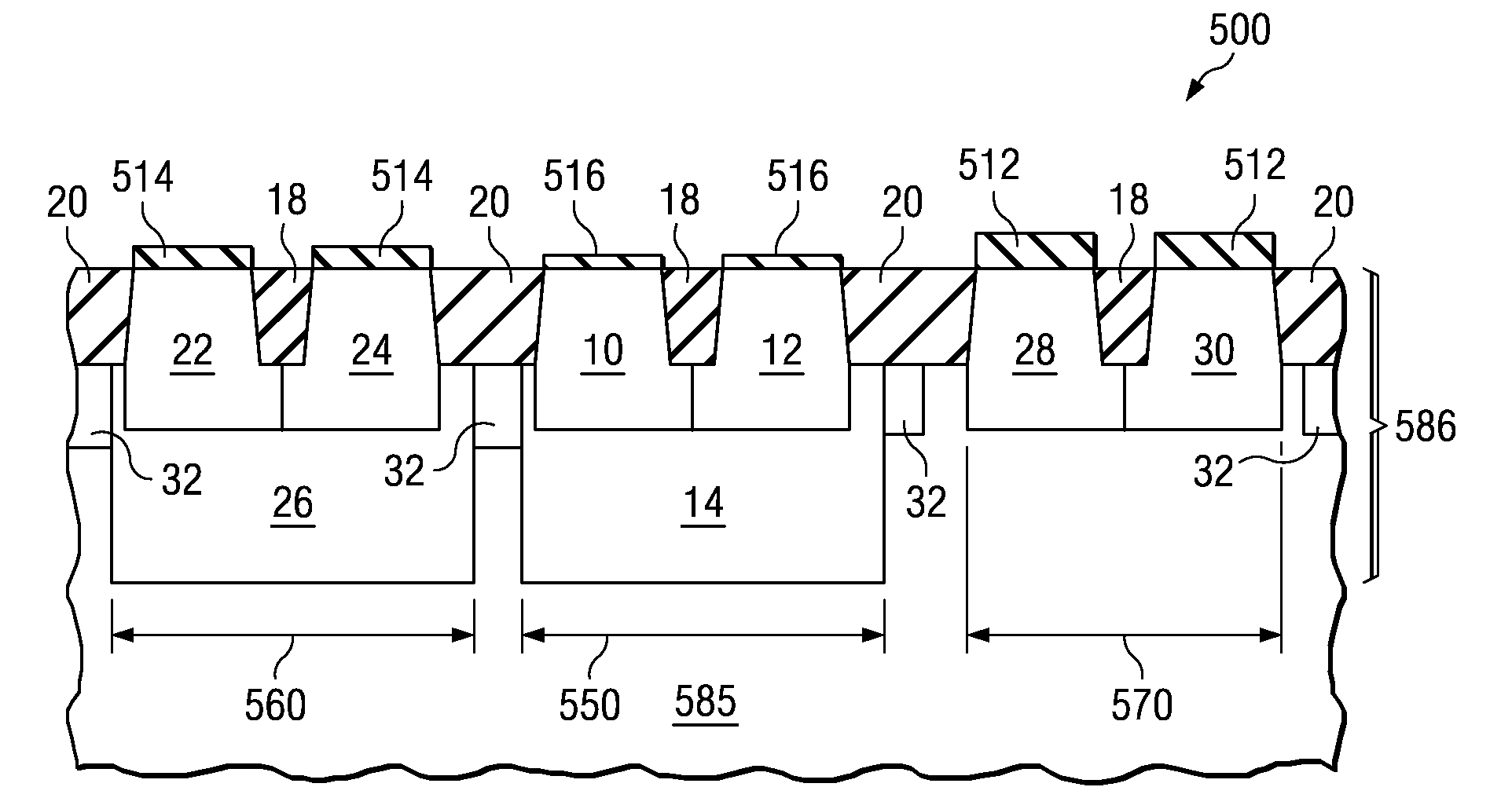
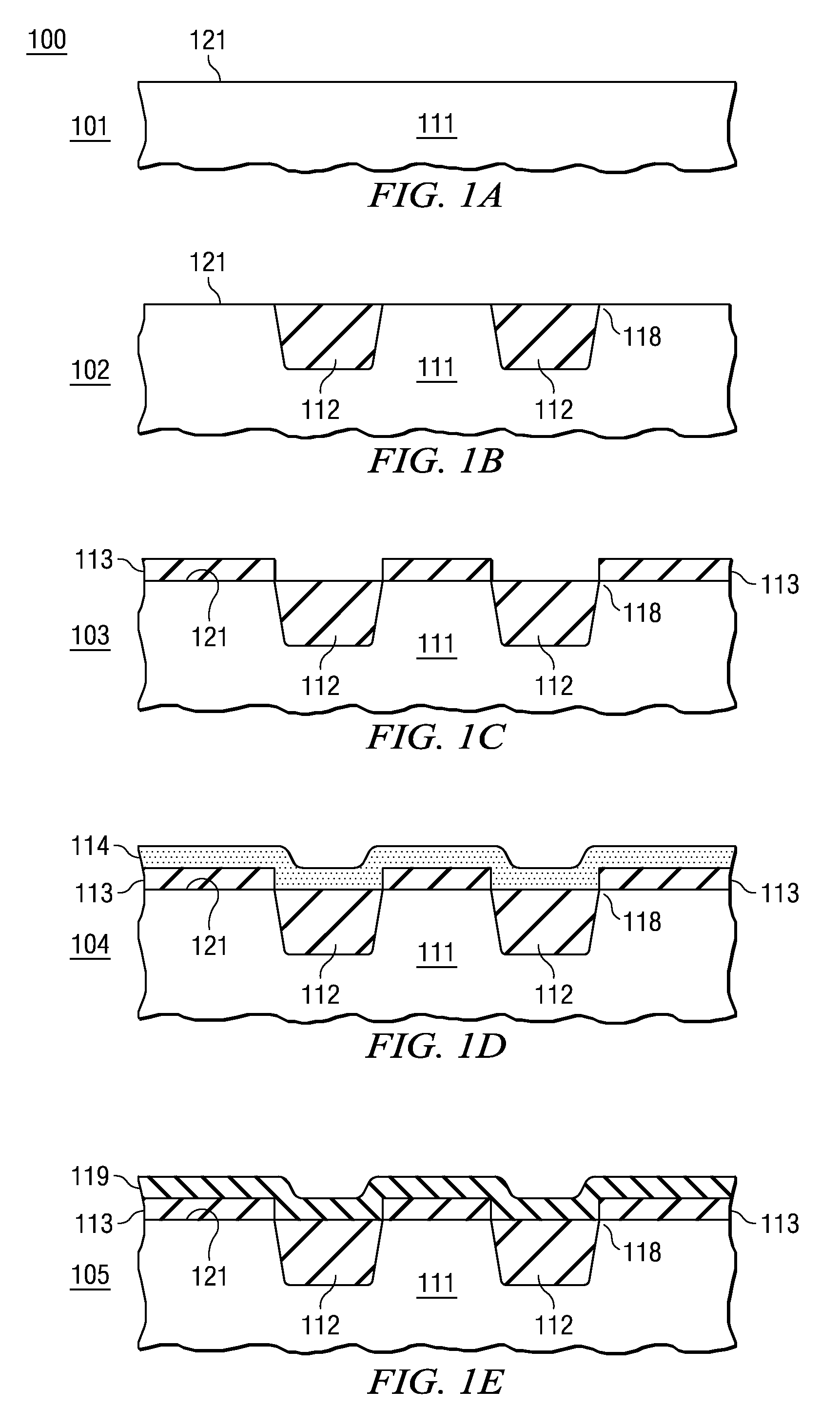
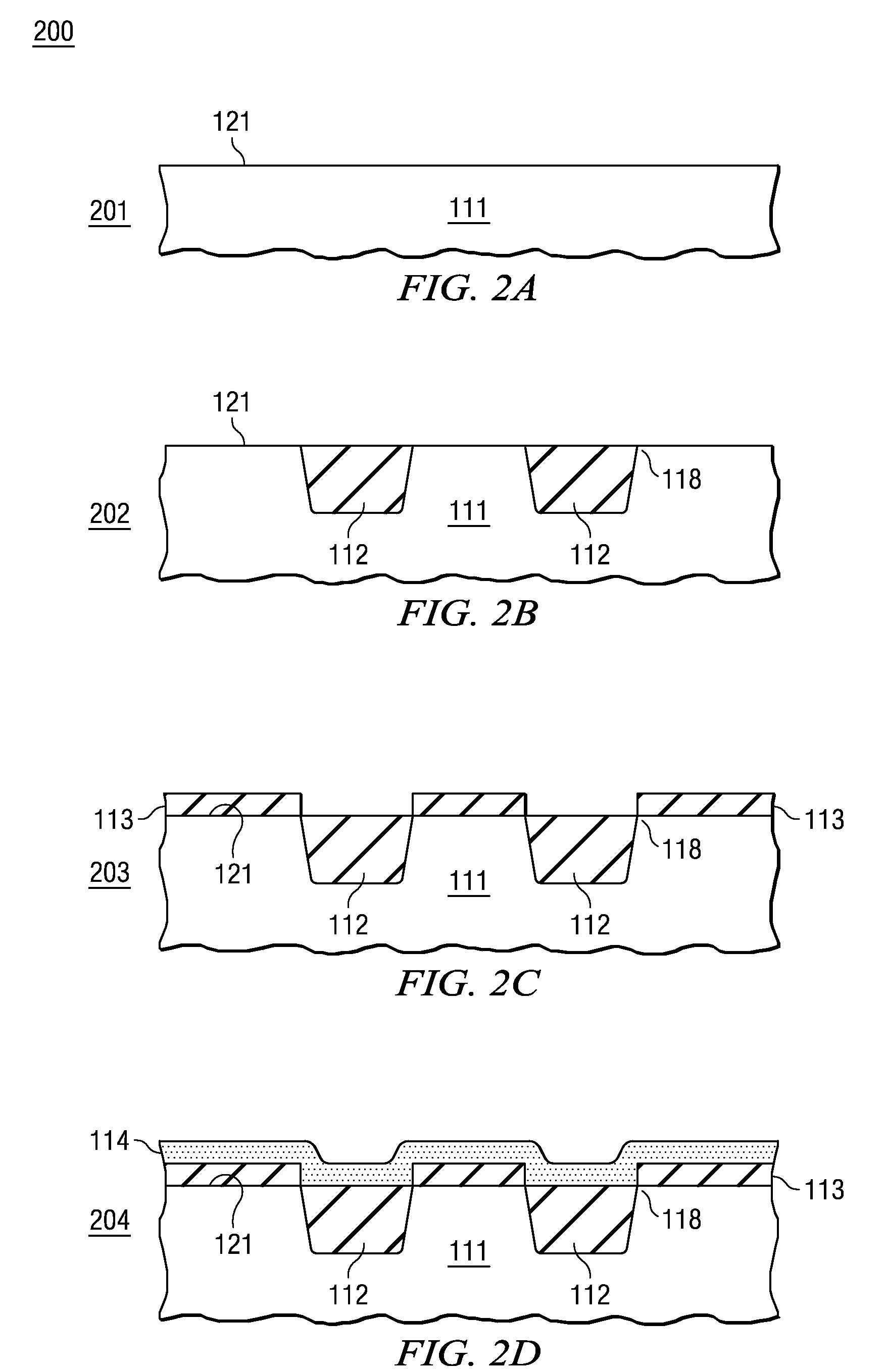
The present invention provides methods for fabricating integrated circuits (ICs) with reduced gate dielectric thinning and corner sharpening at the trench isolation / semiconductor edges, which improves yield and reliability. The method includes depositing a layer of silicon or polysilicon over the trench isolation regions and converting it to a silicon oxide layer to provide at least a portion of the gate dielectric. A patterned gate electrode layer is then formed over the gate dielectric. The invention can include divet reduction processing, such as hard mask pullback processing.

Problems solved by technology

Although steam oxidation, higher temperature, and high pressure oxidation can prevent or at least reduce thinning at the trench isolation edge if target thickness is relatively small by extending the linear oxidation regime, such as up to about 25 to 200 Angstroms, thicker gate oxides needed for higher voltage transistors, such as from 300 to 5,000 Angstroms (e.g. for high voltage transistors 1,000 to 5,000 Angstroms for max Vg of 36 V to 200 V), result in significant thinning at the trench isolation edge which can result in yield loss or reliability problems associated with gate oxide failure.
In addition, since deposited dielectrics are generally deposited at significantly lower temperatures as compared to thermal oxides, deposited dielectrics general exhibit structural inferiority resulting in higher leakage currents and lower breakdown strengths, even if later densified at high temperature.
The oxidation of the grains of varying crystal orientation in the polysilicon generally results in local area variations (i.e. over dimensions of the size of individual grains) of thermally grown oxide thickness of at least 10 angstroms for oxide thickness at least several hundred angstroms thick within localized regions, resulting in significant surface roughness.
Thus, there is likely to be several instances of oxide thickness changing by greater than 100 angstroms, and the top surface of the oxide will not faithfully following the contour of the bottom surface.
However, additional oxidation time should generally be limited due to the corner sharpening that may occur as a result.

Method used


Image

  • Methods for reducing gate dielectric thinning on trench isolation edges and integrated circuits therefrom
  • Methods for reducing gate dielectric thinning on trench isolation edges and integrated circuits therefrom
  • Methods for reducing gate dielectric thinning on trench isolation edges and integrated circuits therefrom

Examples


Embodiment Construction

[0014]The present invention is described with reference to the attached figures, wherein like reference numerals are used throughout the figures to designate similar or equivalent elements. The figures are not drawn to scale and they are provided merely to illustrate the instant invention. Several aspects of the invention are described below with reference to example applications for illustration. It should be understood that numerous specific details, relationships, and methods are set forth to provide a full understanding of the invention. One having ordinary skill in the relevant art, however, will readily recognize that the invention can be practiced without one or more of the specific details or with other methods. In other instances, well-known structures or operations are not shown in detail to avoid obscuring the invention. The present invention is not limited by the illustrated ordering of acts or events, as some acts may occur in different orders and / or concurrently with o...


PUM


Abstract

A method of fabricating an integrated circuit (IC) including a plurality of MOS transistors and ICs therefrom include providing a substrate having a silicon including surface, and forming a plurality of dielectric filled trench isolation regions in the substrate, wherein the silicon including surface forms trench isolation active area edges along its periphery with the trench isolation regions. A first silicon including layer is deposited, wherein the first silicon including extends from a surface of the trench isolation regions over the trench isolation active area edges to the silicon including surface. The first silicon including layer is completely oxidized to convert the first silicon layer to a silicon oxide layer, wherein the silicon oxide layer provides at least a portion of a gate dielectric for at least one of the plurality of MOS transistors. A patterned gate electrode layer is formed over the gate dielectric, wherein the patterned gate electrode layer extends over at least one of the trench isolation active area edges to the silicon including surface, and fabrication is then completed.

Description

FIELD OF THE INVENTION[0001]Embodiments of the present invention relate to methods of manufacturing integrated circuits (ICs) and in particular to methods of manufacturing Metal Oxide Semiconductor (MOS) field effect transistors (FETs) having trench isolation, and ICs therefrom that reduce thermally grown gate dielectric thinning at the trench / active area interfaces.BACKGROUND[0002]One common isolation technique for electrically isolating transistors is based on trench isolation. The trench isolation process is generally more suitable for semiconductor chips having high packing density, as compared to local oxidation (LOCOS) processing. A trench region is formed in conventional semiconductor substrates (e.g. Si) with a depth deep enough for isolating the devices or different wells. In general, trenches are etched using a patterned hard mask material (e.g. silicon nitride) over a pad oxide for masking the active area. A thin liner oxide is generally thermally grown and the trenches a...

Claims


Application Information

Patent Timeline
Patent Type & Authority Applications(United States)
IPC IPC(8): H01L29/78H01L21/762
CPCH01L21/76224H01L21/823857H01L21/823878
Inventor CHATTERJEE, AMITAVASRIDHAR, SEETHARAMANWU, XIAOJUDROBNY, VLADIMIR F.
Owner TEXAS INSTR INC
Learn More