Adaptive design of fixture for thin-walled shell/cylindrical components

a technology of cylindrical components and adaptable design, which is applied in the field of structural mechanics, can solve the problems of machining precision problems, lack of static rigidity and dynamic stability of thin walls, and difficult holding of components while machined, so as to prevent the usual exponential growth of vibration, sufficient supporting rigidity and dynamic stability, and satisfying the demand

Inactive Publication Date: 2010-07-01
UNIV OF SHEFFIELD
View PDF31 Cites 17 Cited by
  • Summary
  • Abstract
  • Description
  • Claims
  • Application Information

AI Technical Summary

Benefits of technology

[0029]Adaptive fixture design satisfies the demand in advanced manufacturing engineering of an agile and flexible fixture combination adaptable to different products with similar structural functions but different detailed shapes and sizes. An important element in the present invention is the pressure element, particularly when in the form of an expansible pneumatic tube, which is inflatable within a stable and safe working range up to 5 times its flat diameter and inflating pressure up to 4 Bar. Helped by this, the fixture is not only adaptive to fit the detailed shape of the component, but also adaptive to fit a considerable range of component sizes up to around 4 times of a nominated component diameter. Another special advantage fr

Problems solved by technology

Such component is difficult to hold while it is machined.
The thin wall lacks sufficient static rigidity and dynamic stability to withstand the cutting force generated in the machining process.
Through lack of shear effects, the thin wall becomes dynamically unstable and liable to vibrate, causing machining precision problems, mainly from the insufficient supporting rigidity, and surface finish problems, mainly from the unstable self-excited vibration between the cutting-tool and workpiece (called hereafter for simplicity “chatter”).
A well-designed static fixture will not help with this situation mainly because, on the one hand, a static fixture precisely fitting most of the shell/cylindrical surface will be expensive and sometimes impossible, and, on the other hand, even if a static fixture is very well designed and fits precisely the at-rest position of a thin-walled component, when excited by the cutting force, the flexible thin wall, mainly mai

Method used


Image

  • Adaptive design of fixture for thin-walled shell/cylindrical components
  • Adaptive design of fixture for thin-walled shell/cylindrical components
  • Adaptive design of fixture for thin-walled shell/cylindrical components

Examples


Embodiment Construction

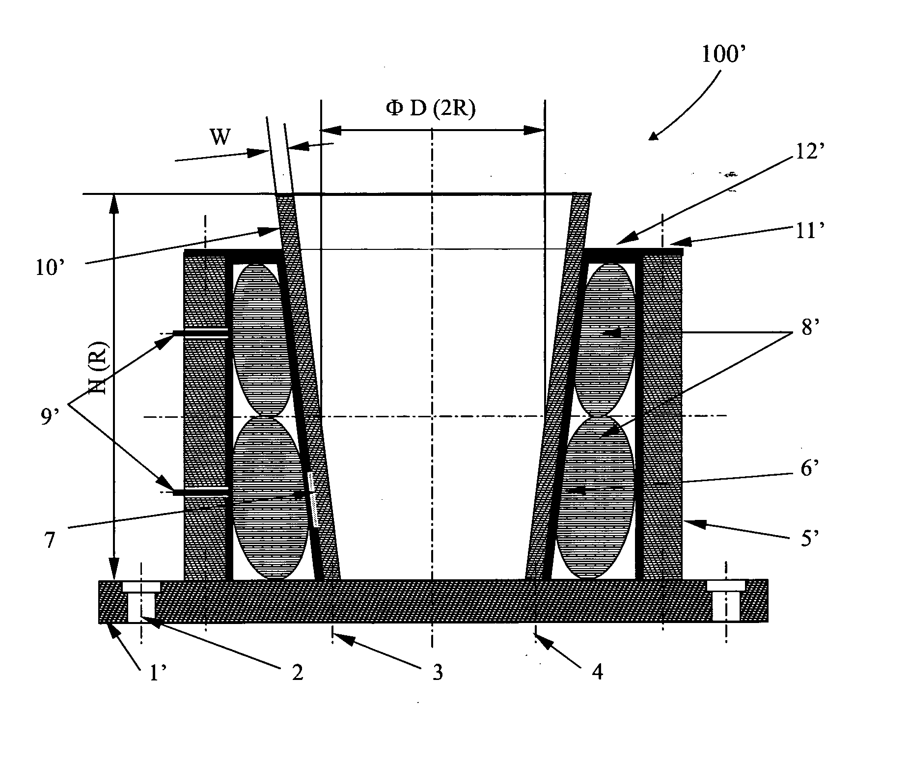
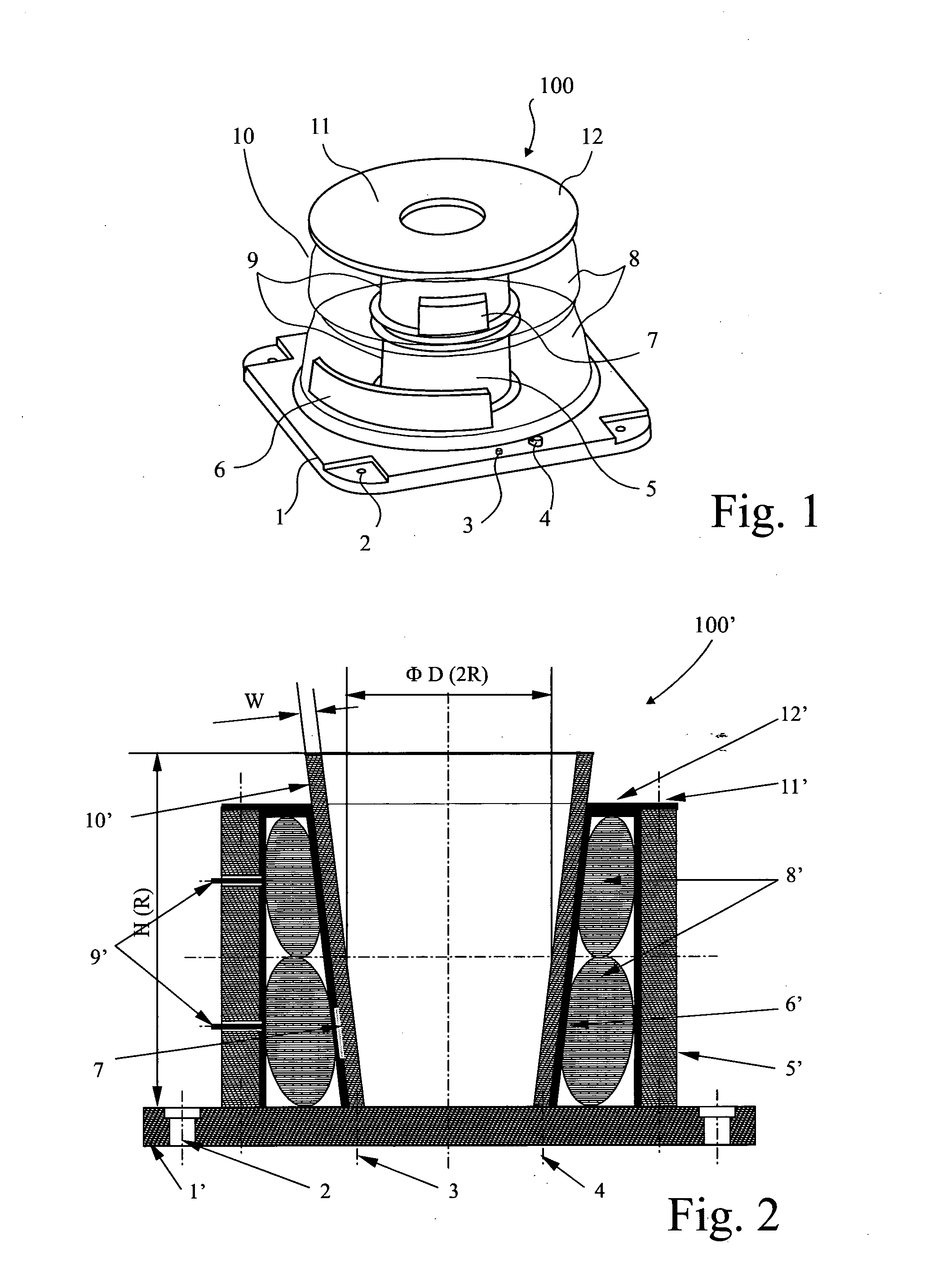
[0043]In FIG. 1, an internal adaptive fixture 100, for the external machining of a thin-walled cylindrical component 10, comprises a mounting base 1 in the form of a thick-walled plate having mounting holes 2 for connection to the machine table (not shown) of a machining centre (not shown). Positioning pins 3 and clamps 4 locate and clamp the component 10 to the base 1.

[0044]A thick-walled rigid arbour or column 5 is fixed centrally of the base 1 by bolts (not shown). The arbour 5 terminates with a flange to connect to a thick-walled lid 12. Two modified vehicle-wheel inner tubes 8, having an internal radius R corresponding with the radius of the arbour 5, are fitted on the arbour. Being made of elastomeric, resiliently flexible material, the tubes 8 can be inflated to fit the enclosure confined within the cylindrical component 10, support arbour 5, mounting base 1 and lid 12. Each tube 8 has its own air inlet valve 9 on its inner surface, and this is fitted through a respective ape...


PUM

PropertyMeasurementUnit
Thicknessaaaaaaaaaa
Thicknessaaaaaaaaaa
Frequencyaaaaaaaaaa

Abstract

A group of fixtures for thin-walled shell/cylindrical components (10) while they are being machined internally and externally, has a mounting base (1) having mounting holes, positioning pins and clamps to locate one end of the thin-walled component. A supporting arbour or cylinder (5) is fixed in the base. A circular lid (12) is fixed to the supporting arbour or cylinder and has a wedged step to locate the other end of the cylindrical component for internal and external machining, or the major open end of shell component for internal machining. A pair of modified vehicle wheel inner tubes (8) are disposed around the supporting arbour or cylinder. A multi-layered sacrificial liner (7) surrounds the pressure element and is adapted to fit between it and the thin-walled components. When properly inflated according to the design and validation procedure, the fixture adaptively holds the thin-walled components for machining, with sufficient supporting rigidity and dynamic stability, so as to maintain the machining precision and surface finish to an acceptable engineering standard. Furthermore, a reasonable and practical design and validation procedure is supplied, easily adapted to different sized thin-walled shell/cylindrical components.

Description

[0001]This invention relates to an adaptive design of fixture for shell / cylindrical components, for the purpose of enabling them to be machined with sufficient supporting rigidity and dynamic stability, so as to maintain the machining precision and surface finish to an acceptable engineering standard. The invention is particularly applicable to thin-walled components where secure fixture and vibration avoidance during machining is difficult to achieve.BACKGROUND[0002]According to the theory of structural mechanics, well known to those skilled in the art, shell / cylindrical components are defined as a group of hollow objects with openings, shaped with continuity and curvature. A bowl-like structure characterises a shell component, having a single major opening, whereas a hollow tubular structure having a through-opening characterises a cylindrical component. Both have a wall that has a wall-thickness, and each has a profile-dimension, which is either its radius, if its diameter is lar...

Claims


Application Information

Patent Timeline
IPC IPC(8): B23B31/30B23Q3/08
CPCB23B31/305B23B2215/64B23Q3/06B23Q17/0976B25B5/065B25B1/20Y10T29/49998Y10T279/1024Y10T279/1029Y10T279/1216G01M7/022Y10T279/1087Y10T279/1283B23B31/30B25B5/06B23Q11/00
Inventor GENG, ZUNMIN
Owner UNIV OF SHEFFIELD
Why Eureka
Try Eureka