Pulsed width modulated control method and apparatus

a control circuit and pulse width technology, applied in the direction of electric controllers, pulse techniques, instruments, etc., can solve the problems of inability to easily adapt to pulsed signal control of motor speed, speed of single-phase motors, and high cost of control circuits

Active Publication Date: 2010-07-01
BCD SHANGHAI MICRO ELECTRONICS CO LTD
View PDF7 Cites 26 Cited by
  • Summary
  • Abstract
  • Description
  • Claims
  • Application Information

AI Technical Summary

Benefits of technology

[0013]Embodiments of the present invention provide methods and apparatus for a pulse-width-modulated (PWM) controller that accepts a pulsed input signal and provides an output PWM control signal which has an adjustable minimum duty cycle. In some embodiments, the duty cycle of the output PWM control signal has a duty cycle correlated to the duty cycle of the pulsed input signal. The input pulsed signal is first converted to an analog signal which has a magnitude correlated to the duty cycle of the pulsed input signal. The PWM output control signals are generated based on a comparison of the analog signal with a triangle wave signal.

Problems solved by technology

As modem personal computers become more powerful, they consume more power and generate more heat.
Even though widely used, conventional techniques for adjusting the speed of single-phase motors have many limitations, such as:1. In some cases, the control signal for motor speed control is an analog signal provided by a temperature sensing device, and can not be easily adapted for pulsed signal control of motor speed.
In this design, the power consumption tend

Method used


Image

  • Pulsed width modulated control method and apparatus
  • Pulsed width modulated control method and apparatus
  • Pulsed width modulated control method and apparatus

Examples


Embodiment Construction

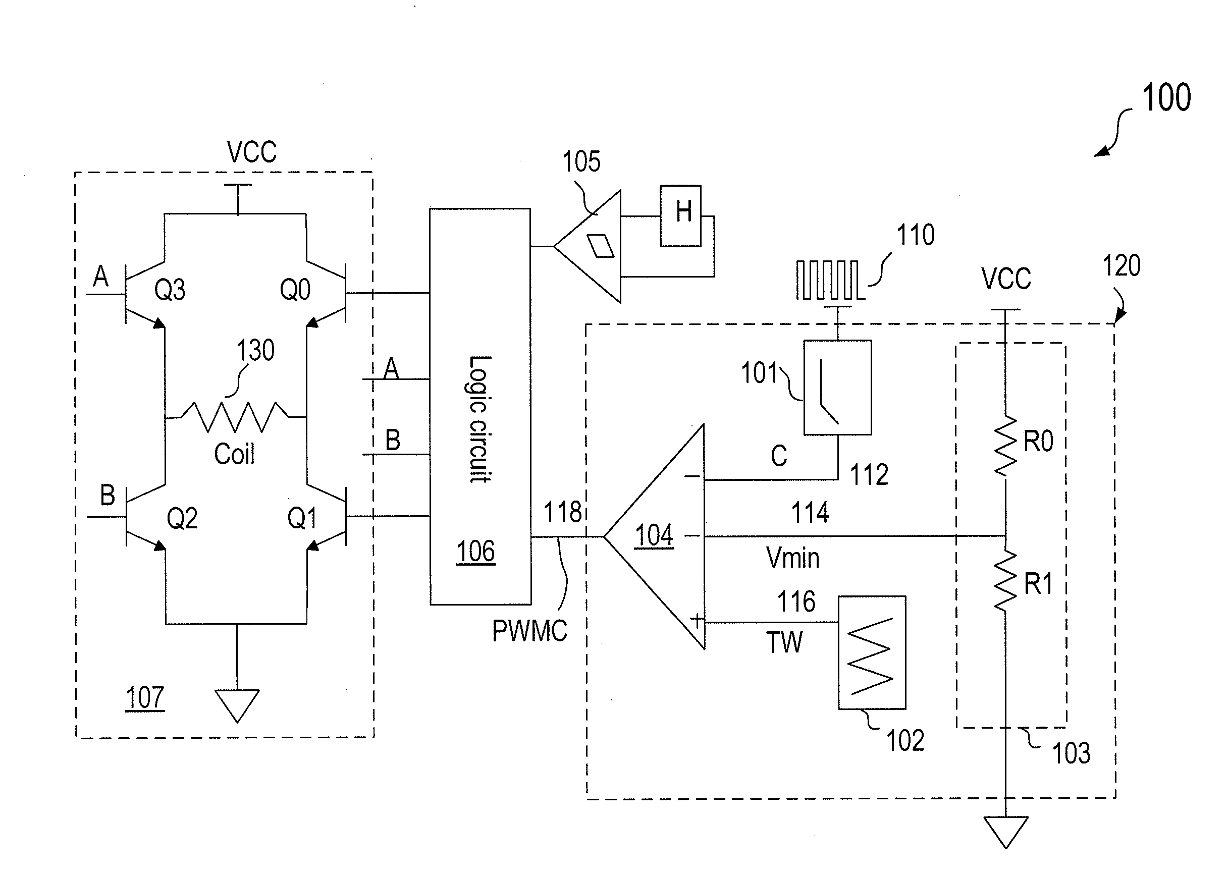
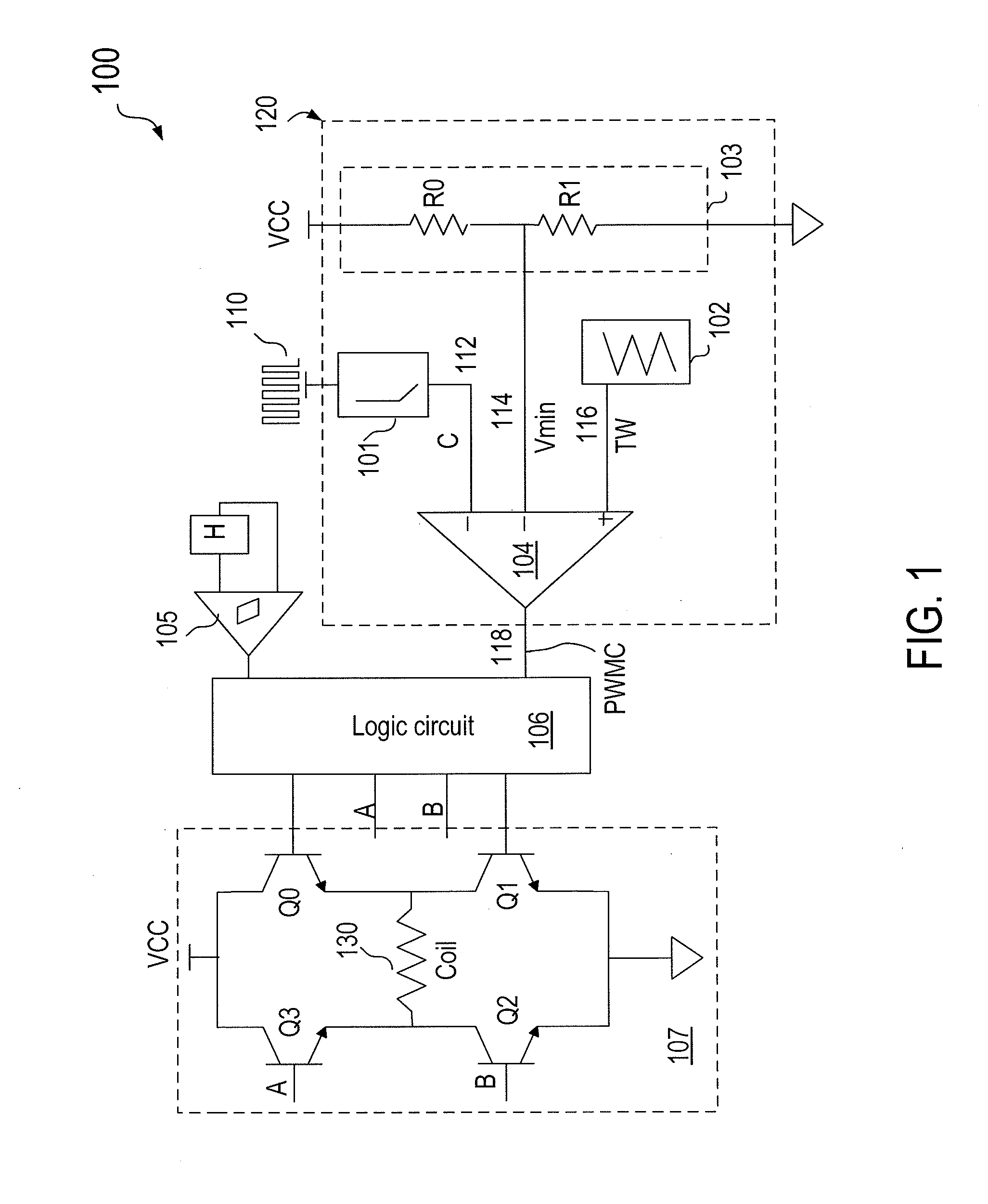
[0030]Embodiments of the present invention provide methods and apparatus for a pulse-width-modulated (PWM) controller that accepts a pulsed input signal and provides an output PWM control signal which has an adjustable minimum duty cycle.

[0031]In some embodiments of the present invention, a PWM fan speed control system can provide one or more of the following functions: (1) accept pulsed input signal and then output PWM signal to control fan speed; (2) the duty cycle of the output PWM control signal has a duty cycle correlated to the duty cycle of the pulsed input signal and the slope between output signal and input signal can be adjusted; and (3) the output PWM signal has a adjustable minimum duty cycle to prevent the system output from falling below a certain minimum output level and allow the system to start at a low supply voltage, regardless of the status of input pulsed signal.

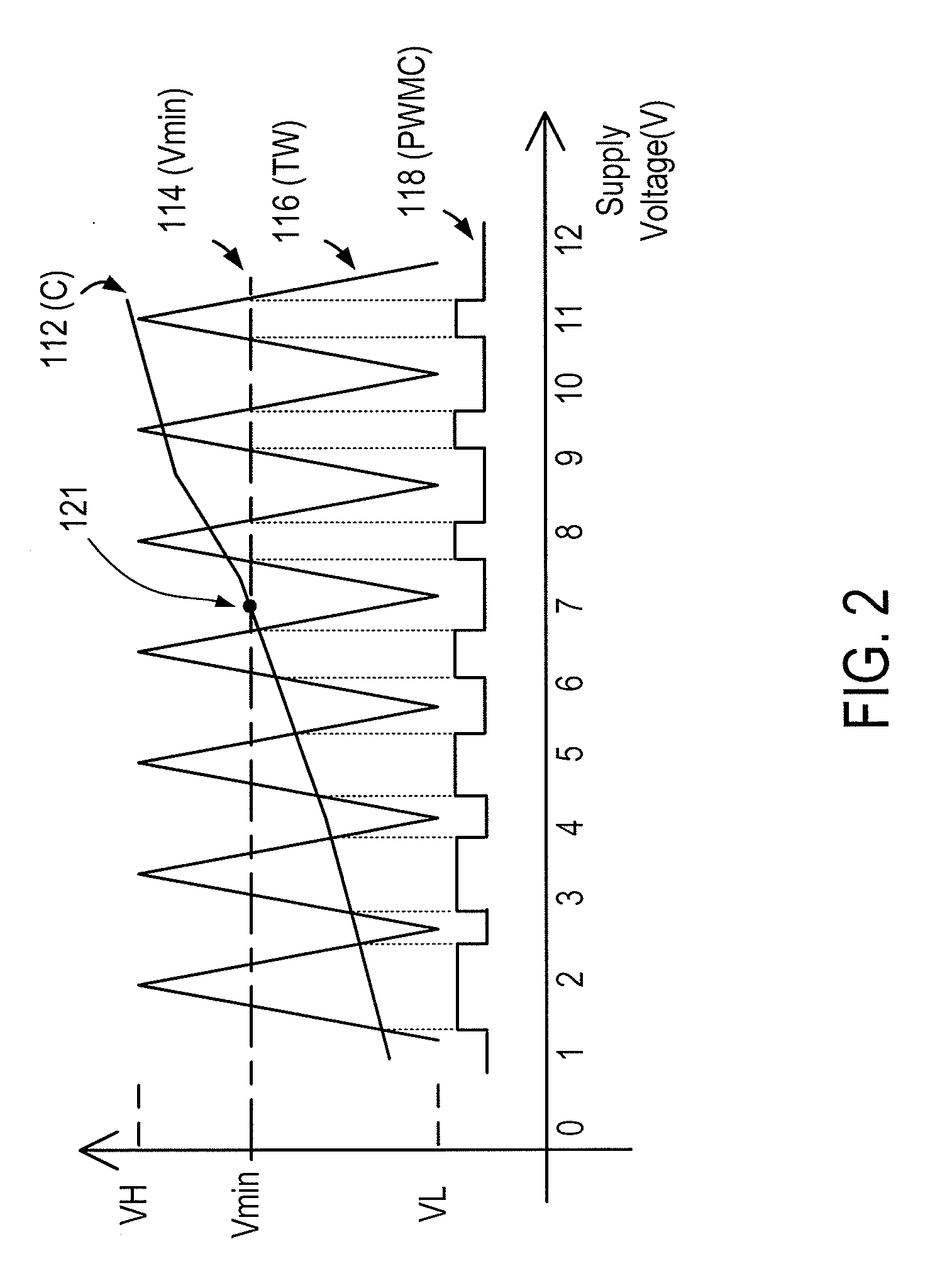
[0032]In PWM control systems, a minimum duty cycle is often provided for setting a minimum output lev...


PUM


Abstract

A pulse width modulated (PWM) controller has an input terminal for receiving a pulsed input signal having a first duty cycle, a power supply terminal for receiving a power supply voltage. a minimum duty cycle reference voltage signal, and a control circuit for providing a pulse-width-modulated (PWM) output signal having a second duty cycle related to the first duty cycle of the pulsed input signal. The PWM output control signal having a minimum duty cycle that is adjustable in response to a change in the power supply voltage. In an embodiment, the second duty cycle and the first duty cycle are correlated in a substantially linear relationship. In an embodiment, the PWM control circuit also has a triangle wave generation circuit for generating a triangle wave signal configured to oscillate between an upper limit voltage and a lower limit voltage, which are adjustable in response to a change in the power supply voltage.

Description

CROSS-REFERENCES TO RELATED APPLICATIONS[0001]This application claims priority to Chinese Patent Application No. 200820129235.0, filed Dec. 31, 2008, which is commonly owned and incorporated herein in its entirety by reference for all purposes. This application is also related to U.S. patent application Ser. No. 12 / 425,366, filed Apr. 16, 2009 and entitled “PWM Control Circuit Having Adjustable Minimum Duty Cycle,” which is commonly owned and incorporated herein in its entirety by reference for all purposes.BACKGROUND OF THE INVENTION[0002]The present invention relates generally to pulse width modulation (PWM) control circuits. More particularly, the invention provides methods and apparatus for a PWM fan motor speed control circuit which accepts a pulsed input signal and provides a PWM output signal having an adjustable minimum duty cycle.[0003]Regulated power sources are indispensable in modem electronics. For example, the power supply in a personal computer often needs to receive ...

Claims


Application Information

Patent Timeline
IPC IPC(8): H03K3/017
CPCH02P6/085H02P27/08F04D27/004H02P6/26Y02B30/70
Inventor ZHANG, ZHIHONGHUANG, XUJIANG
Owner BCD SHANGHAI MICRO ELECTRONICS CO LTD
Why Eureka
Try Eureka