Measuring brillouin backscatter from an optical fibre using channelisation

a technology of optical fibre and backscatter, which is applied in the direction of heat measurement, instrumentation, testing of fibre optic/optical waveguide devices, etc., can solve the problems of large bandwidth degrading performance, slow data acquisition time, and long process, and achieve accurate measurement and rapid measurement. , the effect of high performan

Active Publication Date: 2010-07-01
SCHLUMBERGER TECH CORP
View PDF5 Cites 31 Cited by
  • Summary
  • Abstract
  • Description
  • Claims
  • Application Information

AI Technical Summary

Benefits of technology

[0013]Dividing the Brillouin backscatter signal into multiple frequency components and detecting each component in one of a plurality of parallel detection channels allows the full frequency range of the Brillouin shift to be observed with one probe pulse, but without drawbacks associated with components capable of handling a broadband signal. Distributing the detection over many narrowband channels allows high performance narrowband components to be used, thus giving an accurate measurement. At the same time, the measurement is rapid because all frequencies are detected simultaneously, thus avoiding time-consuming frequency scanning.

Problems solved by technology

A problem with discriminator-based techniques is the need to employ a wide input frequency spectrum to capture the full range of potential output signal frequencies.
The necessary broad bandwidth tends to degrade performance.
For these various scanning methods, the data acquisition time is typically slow, since the signals needs to be averaged in two dimensions.
Depending on the sampling interval in the frequency offset domain and the span of frequencies to be covered, this can be a lengthy process during which essential but sparsely used information is acquired.

Method used


Image

  • Measuring brillouin backscatter from an optical fibre using channelisation
  • Measuring brillouin backscatter from an optical fibre using channelisation
  • Measuring brillouin backscatter from an optical fibre using channelisation

Examples


first example embodiment

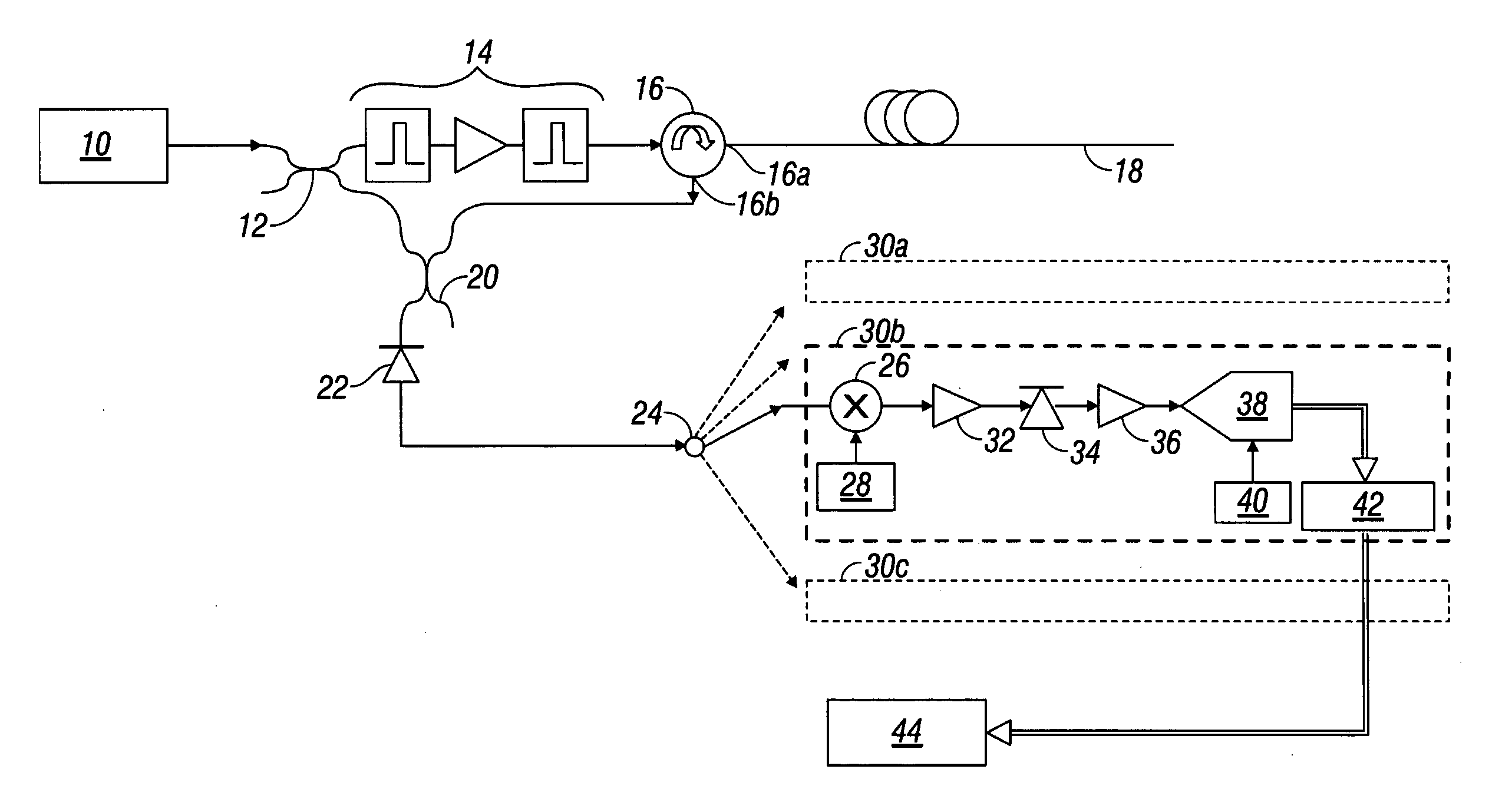
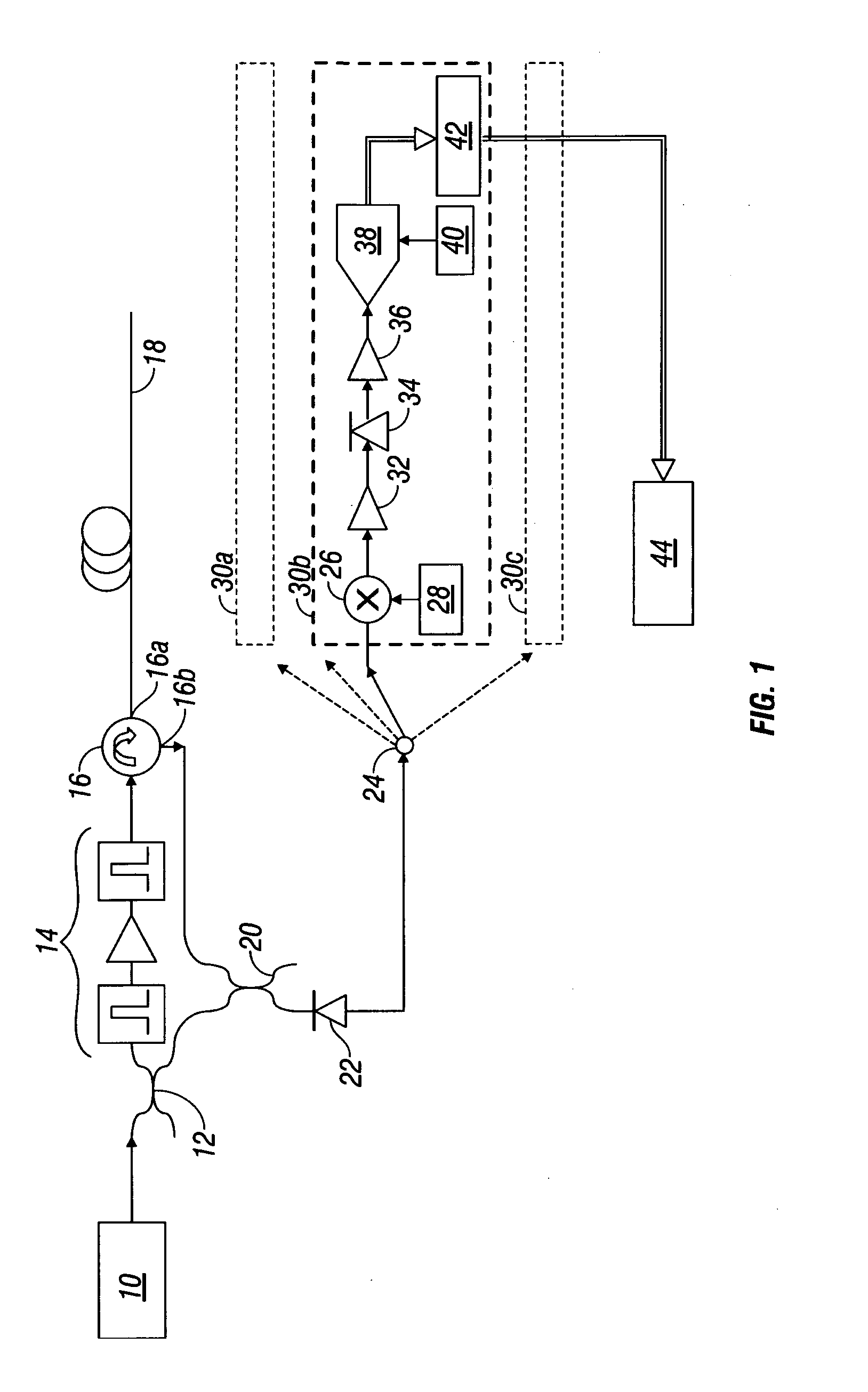
[0028]FIG. 1 shows a schematic representation of apparatus for implementing a measurement method according to an embodiment of the present invention. This example uses electrical detection in the parallel measurement channels.

[0029]An optical source 10 operable to generate narrow-band coherent light (such as a laser) produces an output beam at a frequency f0. The beam is directed into a beam splitter 12 (such as a 3 dB fibre splitter) that divides the output beam into a first part for launching into a deployed optical fibre 18, and a second part to be mixed with light received back from the optical fibre 18. The first part passes through a pulse forming unit 14 that produces optical probe pulses of a desired repetition frequency, pulse duration, and power, suitable for probing of the deployed optical fibre 18 to obtain Brillouin backscatter. In this example the pulse forming unit 14 comprises two pulse generators / gates with an amplifier between. However, any required combination of ...

second example embodiment

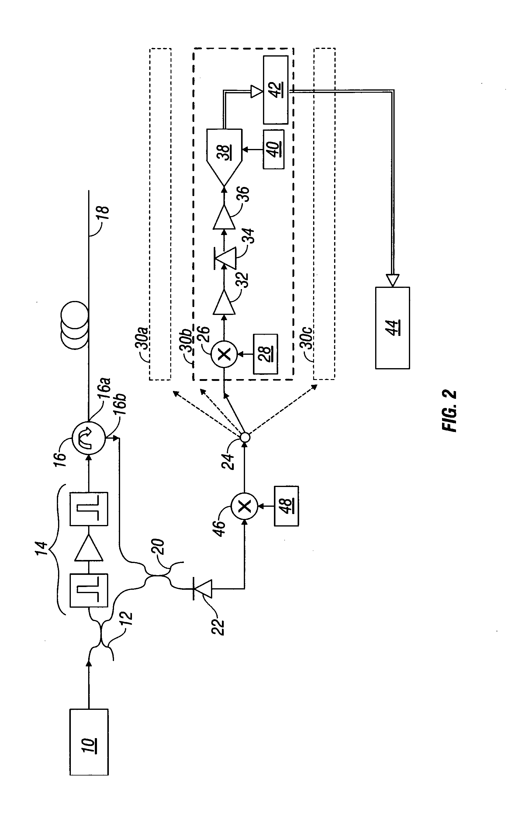
[0043]FIG. 2 shows a schematic representation of a second example of apparatus according to an embodiment of the present invention. This apparatus is substantially the same as that shown in FIG. 1, in that received backscattered light is frequency mixed with other light in an optical detector to produce an electrical difference frequency signal that is then split between a plurality of detection channels distinguished by frequency range, in which the signal is detected and digitized for signal processing.

[0044]However, the apparatus of FIG. 2 further includes a secondary electrical signal mixer 46 disposed between the optical detector 22 and the electrical signal splitter 24. Connected to the secondary electrical signal mixer 46 is a secondary electrical local oscillator 48 operable to generate a secondary electrical signal at a constant frequency fC. The secondary electrical signal mixer 46 receives the primary electrical signal at ΔF(t) from the optical detector. The signal underg...

third example embodiment

[0045]FIG. 3 shows a schematic representation of apparatus according to a further embodiment of the invention.

[0046]The embodiments of FIGS. 1 and 2 utilize an arrangement in which the received backscattered light is converted to an electrical signal by difference frequency mixing before detection. In contrast, FIG. 3 shows an apparatus in which the backscatter is retained in the optical domain for detection.

[0047]As in FIGS. 1 and 2, an optical source 10 generates coherent light at a frequency f0 which is passed through a pulse forming unit 14 that produces probe pulses which are launched into a deployed optical fibre 18 via a first port 16a of an optical circulator 16. However, the returned Brillouin backscatter is not then mixed with another optical signal in an optical detector as in FIGS. 1 and 2. Instead, the second port 16b of the optical circulator 16 is arranged to deliver the backscattered light received from the optical fibre 18 along an optical beam path (defined by an o...


PUM

PropertyMeasurementUnit
difference frequency ΔF(aaaaaaaaaa
frequency ΔF2aaaaaaaaaa
difference frequency ΔF(taaaaaaaaaa

Abstract

A method for measuring Brillouin backscattering comprises obtaining a signal representative of backscattered Brillouin light received from a deployed optical fibre, and dividing the signal into a plurality of signal components each having a different frequency hand. Each signal component is delivered to one of a plurality of parallel detection channels, in which the components are detected, and the signal generated by the detection is sampled using an analog-to-digital converter. The samples are then processed to determine one or more properties of the Brillouin spectral line. Detection may be optical, where the backscattered light is dispersed into a plurality of optical frequency components, or electrical, where the backscattered light is first frequency mixed to downconvert the frequency to the microwave regime.

Description

BACKGROUND OF THE INVENTION[0001]1. Field of the Invention[0002]The present invention relates to a method for measuring Brillouin backscattered light from an optical fibre used for optical time domain reflectometry.[0003]2. Description of Related Art[0004]Optical time domain reflectometry (OTDR) is a technique that uses optical fibre to make remote measurements of various parameters. A probe pulse of light is launched into an end of a fibre that is deployed through a region of interest, for example down an oil well. The pulse propagates along the fibre, and part of the light is backscattered from points along the length of the fibre and returns to the launch end, where it is detected. The propagation time to the scattering point and back is recorded as the light returns, so the location of the scattering point can be calculated using the speed of propagation in the fibre. Also, various physical parameters such as temperature, strain, and pressure have an effect on how the light is s...

Claims


Application Information

Patent Timeline
Patent Type & Authority Applications(United States)
IPC IPC(8): G01N21/00G01N21/55
CPCG01K11/32G01K2011/322G01M11/3127G01D5/35364G01K11/322G01D5/353G01L1/242
Inventor HARTOG, ARTHUR H.
Owner SCHLUMBERGER TECH CORP
Why Eureka
Try Eureka