Heat Exchanger and Method of Making and Using the Same

a technology of heat exchangers and heat exchangers, which is applied in the field of heat exchangers, can solve the problems of cost and/or space, complicated fabrication or the size of heat exchangers, etc., and achieve the effects of high efficiency, cross-sectional, and simple structur

Inactive Publication Date: 2010-07-08
ZESS
View PDF18 Cites 16 Cited by
  • Summary
  • Abstract
  • Description
  • Claims
  • Application Information

AI Technical Summary

Benefits of technology

[0010]The present invention provides several advantages over prior art heat exchangers. One such advantage is that the invention allows for a relatively simplistic method of fabricating a highly efficient heat exchanger. The preferred embodiment of the present invention is configured such that the cross-sectional area of the stream of fluid being cooled decreases as said stream passes through the heat exchanger and, conversely, the cross-sectional area of the stream of fluid being heated increases as said stream passes through the heat exchanger. Assuming the fluid stream being cooled is gaseous, the reduction of the cross-sectional area of said fluid stream has the effect of decrea...

Problems solved by technology

However, increasing the surface area to volume ratio of a heat exchanger can greatly compli...

Method used


Image

  • Heat Exchanger and Method of Making and Using the Same
  • Heat Exchanger and Method of Making and Using the Same
  • Heat Exchanger and Method of Making and Using the Same

Examples


Embodiment Construction

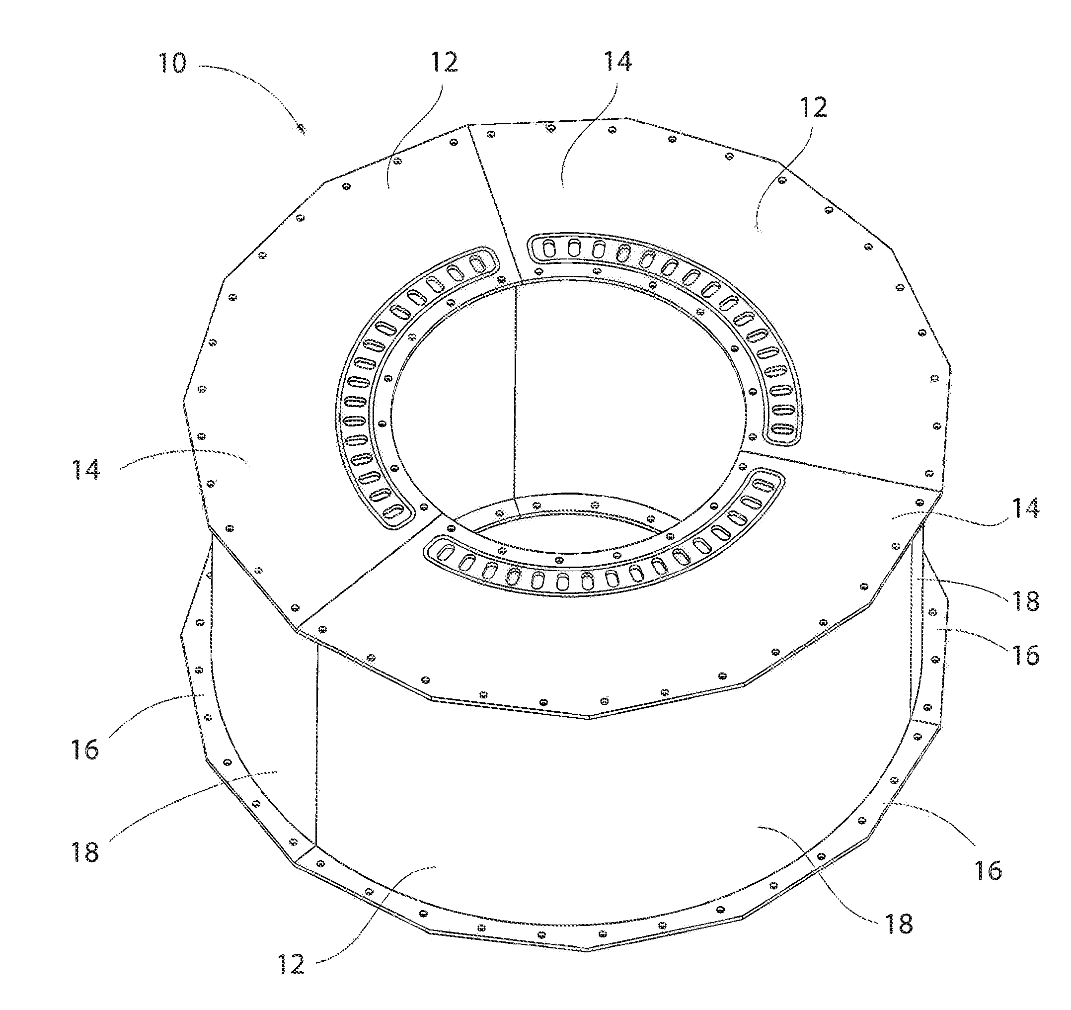
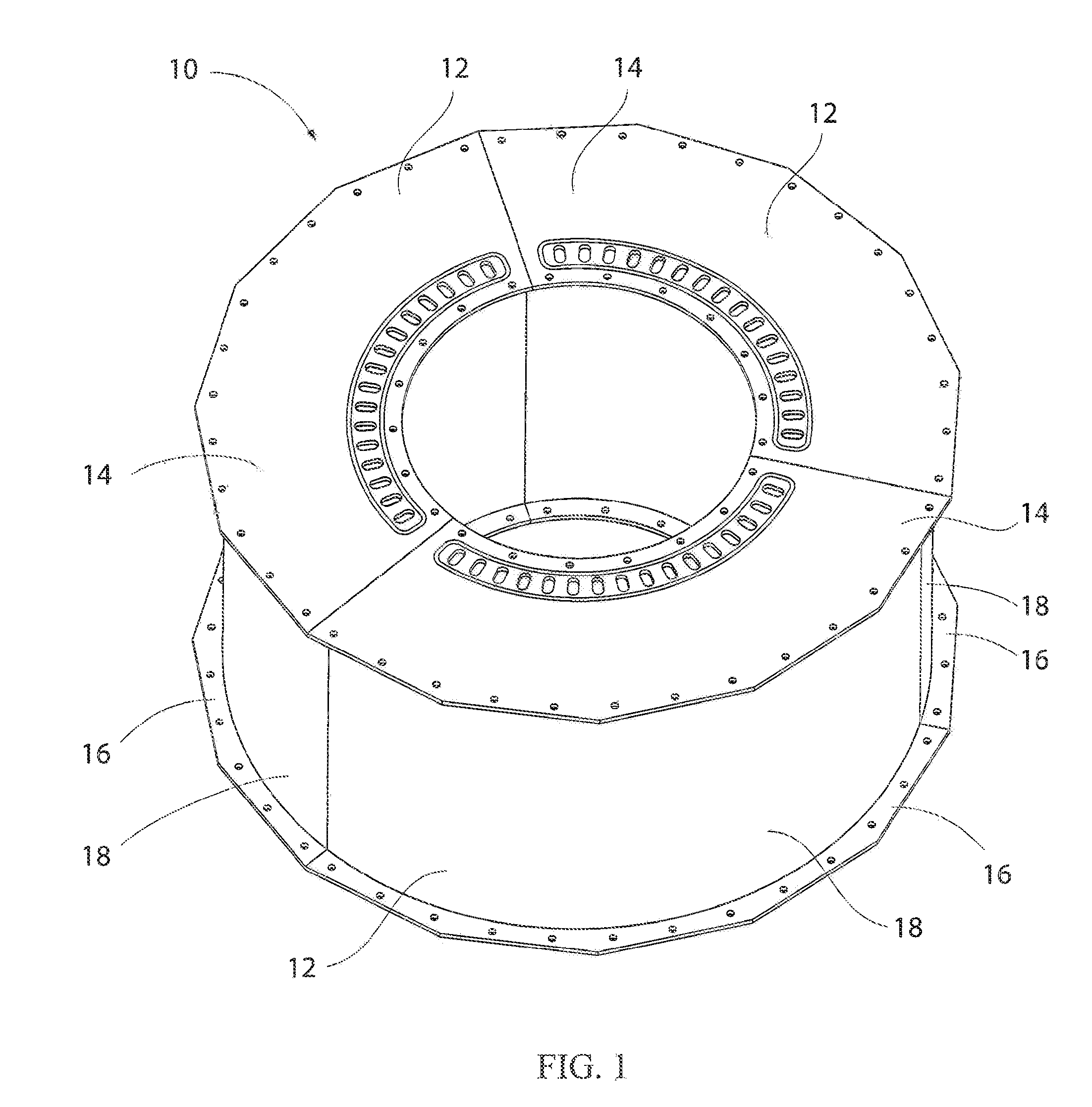
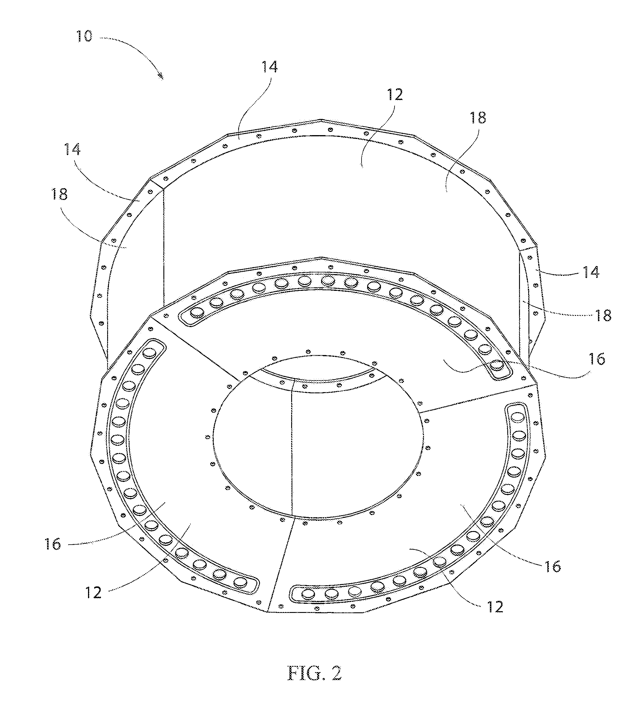
[0029]A heat exchanger in accordance with the present invention is shown in FIGS. 1 and 2. The heat exchanger 10 preferably comprises three identical arcuate subassemblies 12 that together form and annular ring. Each of the subassemblies 12 is capable of operating as a heat exchanger independently of the other subassemblies, but preferably acts in concert with the other subassemblies. For purposes of describing the invention, it should be appreciated that the annular ring defines an axial direction (i.e., any direction parallel to the center axis of the ring), a radial direction (any direction away or toward the center axis), and a circumferential direction (any curvilinear direction that revolves about the center axis). Additionally, the heat exchanger 10 and its components are referred to as having upper / top and lower / bottom elements. It should be appreciated that such adjectives are used merely to explain the orientation of the various elements relative to each other and not rela...


PUM

PropertyMeasurementUnit
Areaaaaaaaaaaa
Gravityaaaaaaaaaa
Distanceaaaaaaaaaa

Abstract

A method of transferring heat from a warmer stream of gas to a cooler stream of gas comprises flowing the warmer stream of gas through a heat exchanger in a manner such that the warmer stream of gas converges as the warmer stream of gas flows through the heat exchanger. The method further comprises flowing the cooler stream of gas through the heat exchanger in a manner such that the cooler stream of gas diverges as the cooler stream of gas flows through the heat exchanger. Another method comprises forming a heat exchanger by solid state welding a plurality of laminate members to each other. The heat exchanger may be a heatsink. The heat exchanger may also condense gas into a liquid.

Description

CROSS-REFERENCE TO RELATED APPLICATIONS [0001]None.STATEMENT REGARDING FEDERALLY SPONSORED RESEARCH OR DEVELOPMENT [0002]Not Applicable.APPENDIX [0003]Not Applicable.BACKGROUND OF THE INVENTION[0004]1. Field of the Invention[0005]This invention pertains to heat exchangers. More particularly, the present invention pertains to heat exchangers that are ideally suited for transferring heat between two gaseous fluids.[0006]2. General Background[0007]Heat exchangers are used in numerous industries and devices for numerous purposes. Many types of heat exchangers rely on the transfer of heat between two fluids. For example, many internal-combustion engines are typically water cooled and typically utilize a heat exchanger (radiator) to transfer heat from the liquid water or coolant to air. Some heat exchangers are gas-to-gas heat exchangers, wherein heat is transferred between two separate streams of gaseous fluid. The steady-state efficiency of a gas-to-gas heat exchanger is typically depen...

Claims


Application Information

Patent Timeline
IPC IPC(8): F28D7/00B23P15/26
CPCF28F2230/00B23K2101/14B23K20/002F28F3/048F28F3/086F28F13/02F28F2275/061H01L23/473H01M8/04014H01M8/04074H01L2924/0002F28F2280/04Y10T29/49393F28D9/0018F28F2255/00Y02P70/56H01L2924/00Y02E60/50Y02P70/50
Inventor ZESS, JAMES ALLENSCHLOTE, ANDREW
Owner ZESS
Why Eureka
Try Eureka