Distributed head-mounted display system
- Summary
- Abstract
- Description
- Claims
- Application Information
AI Technical Summary
Benefits of technology
Problems solved by technology
Method used
Image
Examples
Embodiment Construction
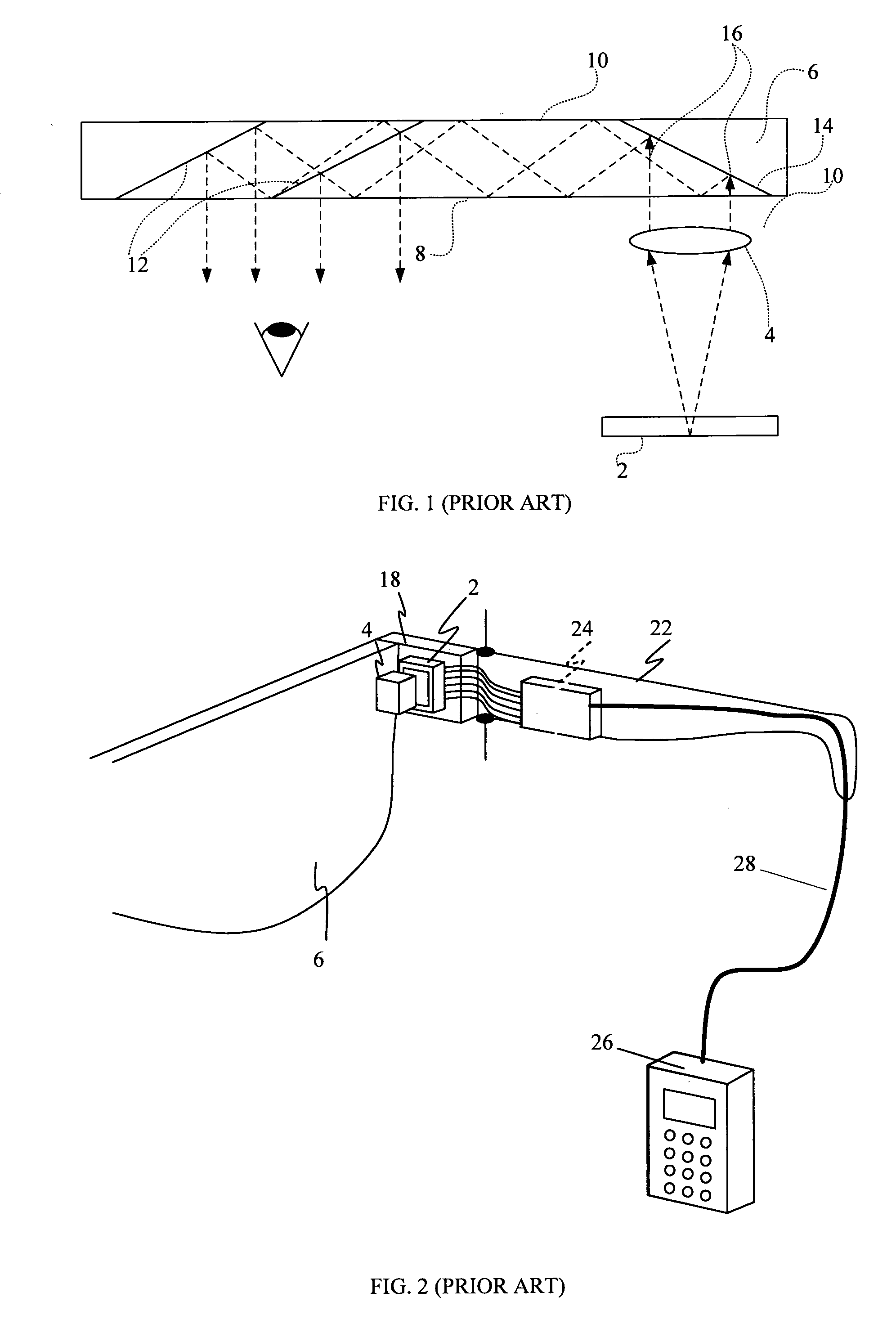
[0020]FIG. 1 illustrates a main optical module comprising a display source 2, a collimating device 4, e.g., a lens, and an LOE 6, to form an optical system. Such an LOE typically includes at least two major surfaces 8 and 10 and edges, at least one partially reflecting surface 12 and an optical element 14 for coupling light thereinto. The output waves 16 from the collimating device 4 enter the LOE 6 through its lower surface 8. The incoming waves (vis-à-vis the LOE) are reflected from the surface 14 and trapped in the LOE. The collimating device 4 can easily be integrated into a single mechanical module which may be assembled independently of the LOE, with fairly relaxed mechanical tolerances.
[0021]In general, all the potential configurations of the LOEs considered in the publications referred to above, offer several important advantages over alternative compact optics for display applications, which include:
1) The input display source can be located very close to the substrate, so ...
PUM
 Abstract
Description
Claims
Application Information
 - R&D
- Intellectual Property
- Life Sciences
- Materials
- Tech Scout
- Unparalleled Data Quality
- Higher Quality Content
- 60% Fewer Hallucinations
Browse by: Latest US Patents, China's latest patents, Technical Efficacy Thesaurus, Application Domain, Technology Topic, Popular Technical Reports.
© 2025 PatSnap. All rights reserved.Legal|Privacy policy|Modern Slavery Act Transparency Statement|Sitemap|About US| Contact US: help@patsnap.com


