Mechanical cvt drive train and control method for earth working vehicle

a technology of mechanical transmission and drive train, which is applied in the direction of gear lubrication/cooling, gear control, instruments, etc., can solve the problems of overheating or over-pressure operation within the hydrostatic variator, affecting the reliability and affecting the operation efficiency of the mechanical cvt system

Inactive Publication Date: 2010-07-08
S O E TECH
View PDF17 Cites 61 Cited by
  • Summary
  • Abstract
  • Description
  • Claims
  • Application Information

AI Technical Summary

Benefits of technology

[0042]iii. in response to a switch back to the first mode from the second mode, re-issuing control signals to the mechanical CVT and to the fuel supply assembly of the internal combustion engine to vary a ratio of the mechanical CVT and an amount of power produced by the internal combustion engine to maintain the speed of the vehicle at the fixed value.
[0043]In another broad aspect the invention provides an earth working vehicle having an internal combustion engine and a driveline for establishing a driving relationship between the internal combustion engine and wheels of the earth working vehicle. The driveline includes a mechanical CVT. The earth working vehicle also has an electronic controller responsive to a shutdown command of the internal combustion engine to issue a control signal to the mechanical CVT to cause the mechanical CVT to downshift.

Problems solved by technology

However, the main problem with existing hydrostatic mechanical CVTs is their lack of reliability.
For example, it is known in the industry that these mechanical CVTs are affected significantly by temperature variations which affect oil viscosity, causing overheat or over-pressure operation within the hydrostatic variator.
Another problem with existing mechanical CVTs is the creation of a power loop in the mechanical CVT variator which drastically increases the load carried by the mechanical CVT system.
This is expensive and complex.

Method used


Image

  • Mechanical cvt drive train and control method for earth working vehicle
  • Mechanical cvt drive train and control method for earth working vehicle
  • Mechanical cvt drive train and control method for earth working vehicle

Examples


Embodiment Construction

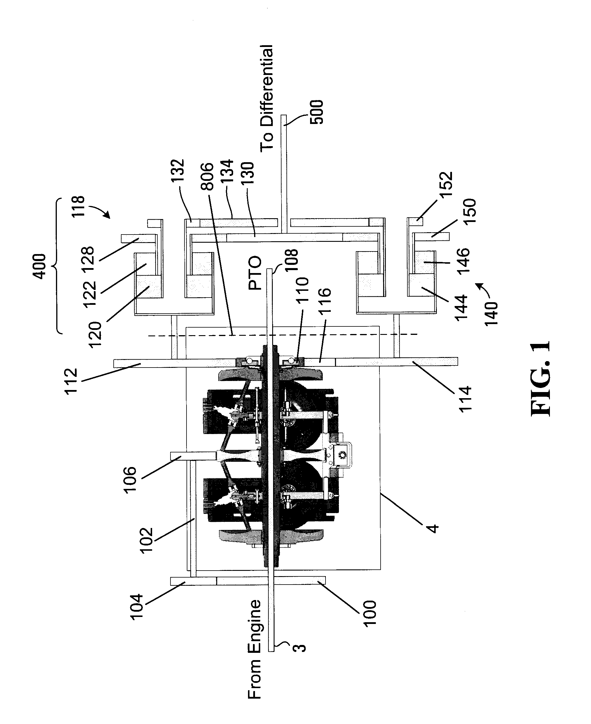
[0062]An embodiment of the driveline unit of an earth working vehicle, such as a tractor, is shown on FIG. 1. The driveline unit allows rotary movement to be communicated from the internal combustion engine to the wheels of the vehicle and optionally to a Power Take Off (PTO) 108. An input shaft 3 is connected directly with the engine. A main gear 100 is keyed to the main shaft 3 and rotates therewith. The main gear 100 drives a secondary shaft 102 via gear 104 that meshes with main gear 100. The secondary shaft 102 brings power to the mechanical CVT 4 via gear 106 that drives the input rotary disk of the mechanical CVT 4. The input shaft 3 extends through the entire mechanical CVT 4 and leads to the PTO 108 such as to drive the PTO 108. The input shaft 3 coinciding with the rotation axis of the main disks of the mechanical CVT 4 (the main disks and the other components of the mechanical CVT 4 will be described later).

[0063]While not shown in the drawings, a main coupling device can...


PUM


Abstract

An earth working vehicle which has an internal combustion engine and a driveline for establishing a driving relationship between the internal combustion engine and wheels of the earth working vehicle. The driveline includes a mechanical CVT. The earth working vehicle also has a control for manual operation by a driver of the earth working vehicle, the control operable by the driver to select among at least two modes of operation, namely a first mode of operation and a second mode of operation, the selection of the first mode of operation corresponding to a command to cause the vehicle to move forward, the selection of the second mode of operation corresponding to a command to cause the vehicle to move backwards. The earth moving vehicle also has an electronic controller. While the vehicle is in motion, the electronic controller is responsive to a change of a mode of operation made via the control and indicating a command to reverse a direction of travel of the vehicle, to issue a control signal to the mechanical CVT to cause the mechanical CVT to downshift.

Description

CROSS-REFERENCE TO RELATED APPLICATION[0001]The present application claims the benefit under 35 USC §119(e) of prior U.S. provisional patent application Ser. No. 60 / 823,361 to Beaudoin, filed Aug. 23, 2006, hereby incorporated by reference herein.FIELD OF THE INVENTION[0002]The present invention generally relates to mechanical transmission systems in earth working vehicles. More specifically, the present invention is concerned with a Continuously Variable Transmission (CVT) system that can be advantageously used in an earth working vehicle such as agricultural, industrial or construction equipment to improve the drivability and the general usefulness of the vehicle.BACKGROUND[0003]Traditionally, earth working vehicles have been designed using multiple ratio geared transmissions such as the one described in the U.S. Pat. No. 5,063,793. As the need for versatility increased, transmissions were provided with greater numbers of gear ratios. To increase drivability, transmission shifting...

Claims


Application Information

Patent Timeline
Patent Type & Authority Applications(United States)
IPC IPC(8): G06F19/00B60K17/08F16H57/04
CPCB60W10/06B60W10/101B60W30/18036E02F9/2025F16H2312/08F16H37/021F16H57/049F16H61/6648E02F9/2246E02F9/2066
Inventor BEAUDOIN, SAMUELDOINNE, JEAN-FRANCOISDESMEAULES, JEAN-ROBERT
Owner S O E TECH
Why Eureka
Try Eureka