Internal combustion engine with exhaust-gas turbocharging

a technology of internal combustion engine and turbocharging, which is applied in the direction of cylinders, charge feed systems, and non-fuel substance addition to fuel, etc., can solve the problems of reducing efficiency, reducing power provided, and observing noticeable torque drop, so as to improve the charge of the combustion chamber, increase the density of exhaust gases, and high recirculation rate

Inactive Publication Date: 2010-07-15
FORD GLOBAL TECH LLC
View PDF8 Cites 18 Cited by
  • Summary
  • Abstract
  • Description
  • Claims
  • Application Information

AI Technical Summary

Benefits of technology

[0003]For engine pressure charging, use is often made of an exhaust-gas turbocharger. The advantages of the exhaust-gas turbocharger, for example in comparison with a mechanical charger, lie in the fact that no mechanical connection is required for transmitting power between the charger and the internal combustion engine. While a mechanical charger extracts the energy required for driving it entirely from the internal combustion engine, and therefore reduces the provided power and in this way reduces efficiency, the exhaust-gas turbocharger utilizes the exhaust-gas energy of the hot exhaust gases.
[0084]To realize high recirculation rates, cooling of the exhaust gas to be recirculated, that is to say a compression of the exhaust gas by cooling, may be imperatively necessary. The density of the recirculated exhaust gas increases as a result of the cooling.

Problems solved by technology

While a mechanical charger extracts the energy required for driving it entirely from the internal combustion engine, and therefore reduces the provided power and in this way reduces efficiency, the exhaust-gas turbocharger utilizes the exhaust-gas energy of the hot exhaust gases.
Specifically, according to the prior art, a noticeable torque drop is observed in the event of a certain rotational speed being undershot.
This effect is undesirable and is one of the most severe disadvantages of exhaust-gas turbocharging.
Here, it is fundamentally possible for the drop in charge pressure to be counteracted by reducing the size of the turbine cross section, and the associated increase in the turbine pressure ratio, though this leads to disadvantages at high rotational speeds.
Any change in direction of the exhaust-gas flow—for example as a result of a curvature of the exhaust line—results in a pressure loss in the exhaust-gas flow, and therefore an energy loss.
The response behavior of the exhaust-gas turbocharging and therefore the dynamic operating behavior of the internal combustion engine deteriorate with increasing line length.
The latter in particular cannot be realized in a satisfactory manner in practice when using an exhaust-gas turbocharger.
As a result, the intake downstream of the compressor has not only an undesirably long length, and therefore an undesirably high line volume, but rather also numerous curves which deflect the compressed combustion air.
The result of this approach is a noticeable pressure drop in the combustion air.
The above statements make it clear that there is a conflict of aims between firstly the arrangement of the turbine and secondly the arrangement of the compressor.
This is because, if the compressor were arranged in an optimum manner corresponding to its demands, it would not be possible to maintain the position of the turbine on the exhaust-gas side close to the outlet of the internal combustion engine, and the position of the turbine would have to be relocated to the intake side.
The pressure loss downstream of the compressor and upstream of the turbine is limited.
In contrast, the supply of the exhaust gas by means of a spiral or worm housing requires that the exhaust gas or the exhaust-gas flows be deflected multiple times with significant changes in direction, which results in a pressure loss in the exhaust-gas flow.

Method used


Image

  • Internal combustion engine with exhaust-gas turbocharging
  • Internal combustion engine with exhaust-gas turbocharging

Examples


Embodiment Construction

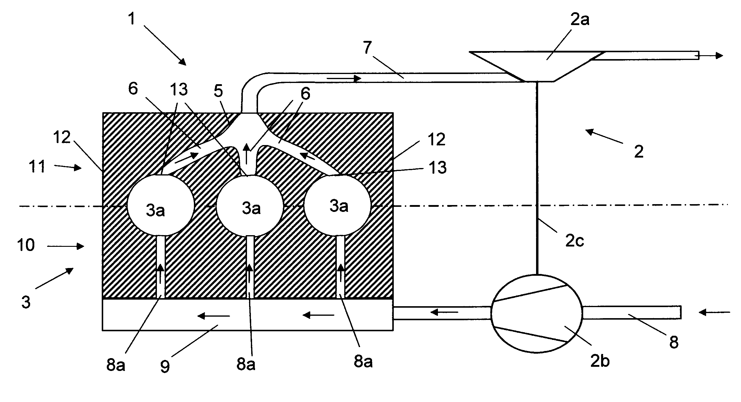
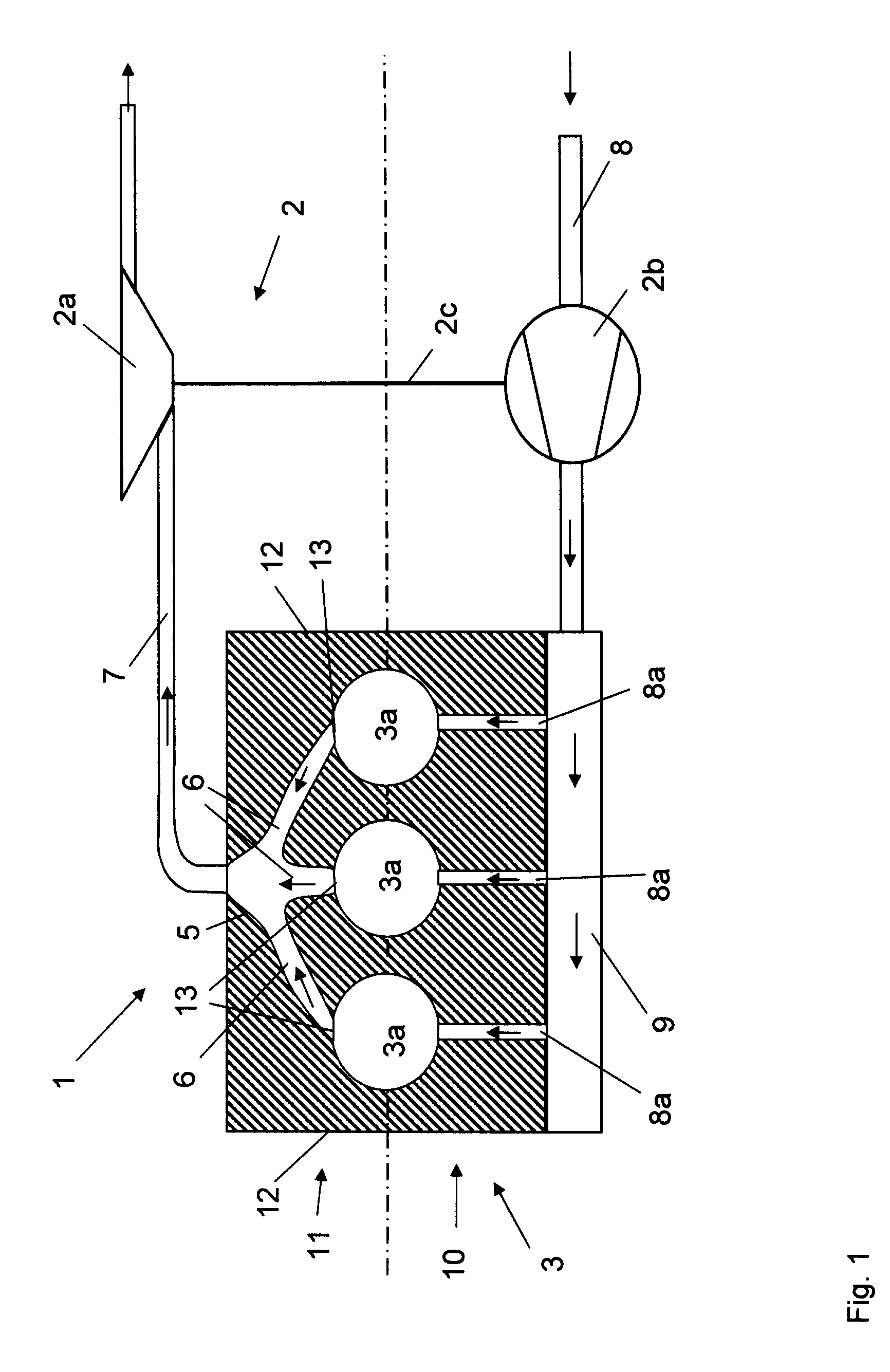
[0086]FIG. 1 shows a first embodiment of the turbocharged internal combustion engine 1 on the basis of the example of a three-cylinder engine.

[0087]The internal combustion engine 1 has a cylinder head 3 with three cylinders 3a which are arranged along the cylinder head longitudinal axis 4 and each of which has an outlet opening 13 adjoined by an exhaust line 6 for discharging the exhaust gases out of the cylinder 3a. The exhaust lines 6 of the three cylinders 3a are merged on the outlet side 11, so as to form an integrated exhaust manifold 5 within the cylinder head 3, to form an overall exhaust line 7.

[0088]To supply the internal combustion engine 1 with fresh air or fresh mixture, an intake 8 is provided on the inlet side 10, which intake 8 opens out into a plenum 9 from where three intakes 8a provide a supply to the cylinders 3a.

[0089]The internal combustion engine 1 is fitted with an exhaust-gas turbocharger 2 which comprises a turbine 2a, which is arranged in the overall exhau...


PUM


Abstract

Disclosed is a turbocharged internal combustion engine (1) having at least one intake (8) for supplying the internal combustion engine (1) with fresh air or fresh mixture on an inlet side (10), a cylinder head (3) having at least two cylinders (3a) which are arranged along a cylinder head longitudinal axis (4) and each of which has at least one outlet opening (13) which is adjoined by an exhaust line (6) for discharging the exhaust gases out of the cylinder (3a), with the exhaust lines (6) of at least two cylinders (3a) being merged on an outlet side (11), so as to form an integrated exhaust manifold (5) within the cylinder head (3), to form an overall exhaust line (7), and at least one exhaust-gas turbocharger (2) which comprises a turbine (2a) arranged in the overall exhaust line (7) and a compressor (2b) arranged in the at least one intake (8), with the turbine (2a) having a turbine rotor, which is provided on a charger shaft (2c), and an inlet region for supplying the exhaust gas, and the compressor (2b) having a compressor rotor, which is arranged on the charger shaft (2c), and an outlet region for discharging the compressed combustion air.

Description

BACKGROUND AND SUMMARY [0001]The present disclosure relates to a turbochaged internal combustion engine having at least one intake for supplying the internal combustion engine with fresh air or fresh mixture on an inlet side, a cylinder head having at least two cylinders which are arranged along a cylinder head longitudinal axis and each of which has at least one outlet opening which is adjoined by an exhaust line for discharging the exhaust gases out of the cylinder, with the exhaust lines of at least two cylinders being merged on an outlet side, so as to form an integrated exhaust manifold within the cylinder head, to form an overall exhaust line, and at least one exhaust-gas turbocharger which comprises a turbine arranged in the overall exhaust line and a compressor arranged in the at least one intake, with the turbine having a turbine rotor, which is provided on a charger shaft, and an inlet region for supplying the exhaust gas, and the compressor having a compressor rotor, whic...

Claims


Application Information

Patent Timeline
Patent Type & Authority Applications(United States)
IPC IPC(8): F02B33/44F02F1/10
CPCF02B29/0406F02B33/44F02F1/243F05B2220/40F02M25/0709F02M25/0727F02M25/0707F02M26/05F02M26/06F02M26/23
Inventor STEINER, BERNDKUHLBACH, KAI SABASTIAN
Owner FORD GLOBAL TECH LLC
Why Eureka
Try Eureka