
Magnetic force sensor

a magnetic force sensor and sensor technology, applied in the field of force sensors, can solve the problems of durability and reliability, difficult to obtain high sensitivity, and size and cost reduction, and achieve the effects of reducing the generation of noise sources, high permeability, and high reliability against magnetic nois

Inactive Publication Date: 2010-07-15
CANON KK
View PDF11 Cites 43 Cited by
  • Summary
  • Abstract
  • Description
  • Claims
  • Application Information

AI Technical Summary

Benefits of technology

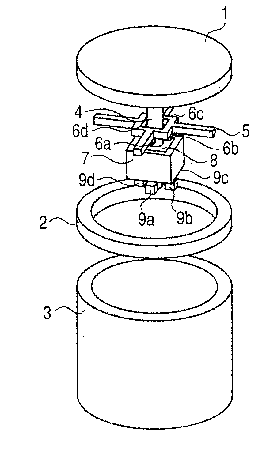
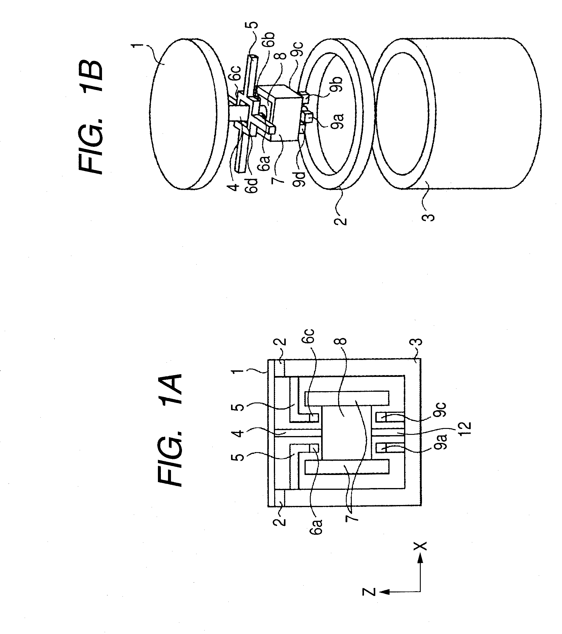
[0011]The magnetic force sensor according to the present invention can control magnetic flux from the magnetic flux generation source with the magnetic body by disposing the magnetic body on an outer-periphery portion of the sensing unit including the magnetic flux generation source and the magnetoelectric transducer.
[0012]By disposing the magnetic body at the outer-periphery portion of the magnetic flux generation source, a structure capable of facilitating, with the magnetic body, trapping of magnetic fluxes generated from the magnetic flux generation source is constructed, thus suppressing generation of a noise source having an adverse effect on the outside.
[0013]When magnetic noise from the outside flows in, the magnetic noise preferentially invades into a magnetic body having high permeability, which makes such a structure that a magnetoelectric transducer cannot obtain, thus attaining high reliability against magnetic noise.
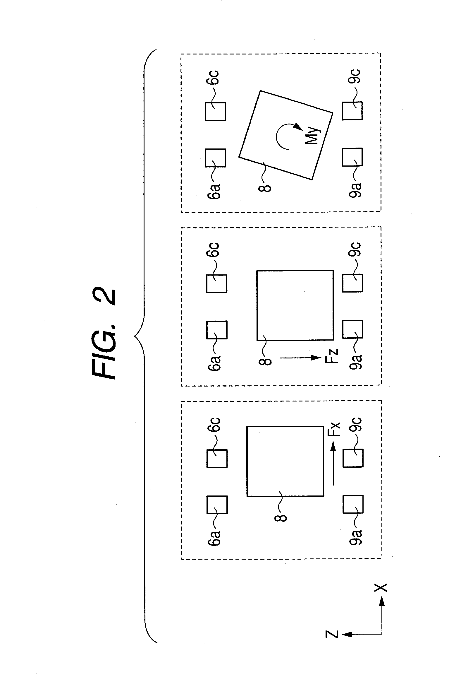
[0014]In addition, magnetic fluxes flowed into the magnetoelectric transducer can be concentrated and therefore, even if a positional displacement of the magnetic flux generation source is very small, a relatively large change in magnetic fluxes is obtained, thereby increasing sensitivity.
[0015]As described above, the present invention provides a magnetic force sensor which detects force / moment in 6-axis directions with a structure which can suppress an adverse effect of an magnetic flux generation source on the outside, improve reliability against noise and increase sensitivity.

Problems solved by technology

Accordingly, when a strained portion receives a force, there occurs a problem of interference between axes axial strain occurs not only in a direction where a force works but also no force works.
In addition, reducing the shaft interference requires to devise a beam structure and signal processing, which are disadvantageous in size and cost reductions.
Further, a strain gauge uses a strain generated when a force is applied and therefore repeated use will cause a problem with durability and reliability due to secular changes.
However, such a structure that a magnetic material faces a magnetoelectric transducer scatters magnetic flux and therefore, a displacement of magnetic flux density detected by the magnetoelectric transducer occurs only a little, which makes it difficult to obtain high sensitivity.
Further, the magnetic material is embedded simply with an elastic body, which causes problems such as generation of a noise source having an adverse effect on peripheral apparatuses and external magnetic flux easily flowing into the magnetoelectric transducer having an adverse effect on output.

Method used


Image

  • Magnetic force sensor
  • Magnetic force sensor
  • Magnetic force sensor

Examples


first embodiment

[0042]FIGS. 3A and 3B illustrate a result of magnetic field simulation, respectively. The simulation was performed with a Z-axisymmetric secondary static magnetic field model. FIG. 3A illustrates that a magnetic flux generation source is disposed, in the air, with 4 mm thickness in Z-axis direction, 2 mm thickness in X-axis direction (1 mm thickness in X-axis direction of the magnetic flux generation source illustrated because the magnetization direction axis meets Z-axis). FIG. 3B illustrates that the magnetic flux generation source is disposed with a magnetic body of 4 mm thickness in Z-axis direction and 1 mm thickness in X-axis direction. For the magnetic flux generation source, the characteristics of Nd—Fe—B magnet having residual magnetic flux density of 1.4T and coercitivity of 1000 kA / m were defined and the relative permeability of the magnetic body was set to 5000.

[0043]FIG. 3A illustrates a configuration of only a magnetic flux generation source in the air. This configurat...

second embodiment

[0048]FIGS. 6A and 6B illustrate a result of magnetic field simulation, respectively. FIG. 6B illustrates a layout of the magnetic body when a thickness thereof in Z-axis direction is changed from 4 mm to 6 mm so as to be larger than a thickness of the magnetic flux generation source 8 in Z-axis direction. Conditions of FIG. 6A are the same as Experimental Example 1 of FIG. 3A.

[0049]The magnetoelectric transducer is located at a distance of 500 μm in X-axis direction and 500 μm from the magnetic flux generation source in Z-axis direction to measure X-component of a magnetic field. If variations in X-component of magnetic flux density appearing at the magnetoelectric transducer when the magnetic flux generation source is displaced by ±50 μm in X-axis direction or ±50 μm in Z-axis direction are taken as ΔBxx and ΔBxz, respectively, graphs as illustrated in FIGS. 7 and 8 are obtained. An arrow on FIGS. 6A and 6B indicates a plot position. FIG. 7 illustrates that a displacement in magne...


PUM

PropertyMeasurementUnit
distanceaaaaaaaaaa
forceaaaaaaaaaa
magnetic fluxaaaaaaaaaa

Abstract

A magnetic force sensor includes: an action portion on which an external force acts; a sensing unit converting a force working on the action portion into an electric signal; and an outer frame having an elastic body elastically supporting the action portion and storing the sensing unit therein. The sensing unit includes a magnetic flux generation source connected with the action portion and a magnetoelectric transducer fixed on the outer frame and the magnetic flux generation source has a magnetic body therewith that controls flow of magnetic fluxes generated by the magnetic flux generation source.

Description

TECHNICAL FIELD[0001]The present invention relates to a force sensor for detecting force / moment 6 direction components and, in particular, relates to a magnetic force sensor for detecting a magnetic flux change in a magnetic flux generation source with a magnetoelectric transducer.BACKGROUND ART[0002]A force sensor is mounted on a wrist portion of a robot arm, for example, in assembling parts with the robot arm, and is used to detect a force / moment component generated during the assembly work and perform posture control of a hand portion of the arm. A conventional typical force sensor makes detection from a resistance change in a strain gauge, as disclosed in Japanese Patent Application Laid-Open No. H01-262431. In addition, there is also another force sensor using a method of magnetically detecting a displacement of an action portion, as disclosed in Japanese Patent Application Laid-Open No. 2004-325328.[0003]First, FIG. 11 illustrates a conventional structural example described in...

Claims


Application Information

Patent Timeline
Patent Type & Authority Applications(United States)
IPC IPC(8): G01L1/12
CPCG01L5/164G01L1/14
Inventor SATO, SHUUICHI
Owner CANON KK
Learn More